REAR WHEEL ALIGNMENT ADJUSTMENT

PROCEDURE
-
INSPECT TIRES
-
MEASURE VEHICLE HEIGHT
-
INSPECT TOE-IN
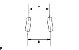
Standard Toe-in (Unloaded Vehicle) except Rough Road Package 1 Item Specified Condition Toe-in B - A: 1.8 +/-2 mm (0.07 +/-0.08 in.) Standard Toe-in (Unloaded Vehicle) for Rough Road Package 1 Item Specified Condition Toe-in B - A: 0.3 +/-2 mm (0.01 +/-0.08 in.) If the toe-in is not within the specified range, inspect the suspension parts and replace them if necessary.
-
ADJUST TOE-IN (for Cam Type)
-
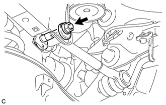
Loosen the nut of the rear No. 1 suspension arm assembly (at the rear suspension member side).
Note
Hold the rear suspension toe adjust cam sub-assembly while rotating the nut.
-
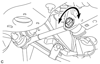
Rotate the rear suspension toe adjust cam sub-assembly to adjust the toe-in.
Adjustment Value except Rough Road Package 1 Item Specified Condition Toe-in B - A: 1.8 +/-2 mm (0.07 +/-0.08 in.) Adjustment Value for Rough Road Package 1 Item Specified Condition Toe-in B - A: 0.3 +/-2 mm (0.01 +/-0.08 in.) Tech Tips
Rotating the rear suspension toe adjust cam sub-assembly by one notch changes the toe by approximately 3.4 mm (0.134 in.).
-
Tighten the nut of the rear No. 1 suspension arm assembly (at the rear suspension member side).
- Torque:
- 100 N*m { 1020 kgf*cm, 74 ft.*lbf }
Note
-
Hold the rear suspension toe adjust cam sub-assembly while rotating the nut.
-
Make sure that all tires of the vehicle are on the ground and the vehicle is unloaded.
-
-
ADJUST TOE-IN (for Turnbuckle Type)
-
Inspect the rear No. 1 suspension arm by inspecting the nuts and adjusting tube for looseness visually and by hand.
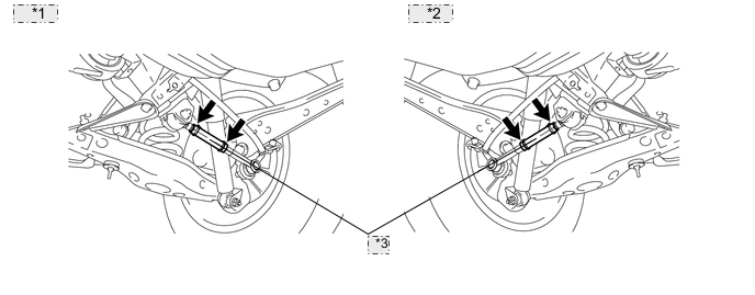
*1 for LH: *2 for RH: *3 Adjusting Tube -
Put matchmarks onto the rear No. 1 suspension arm assembly as shown in the illustration below.
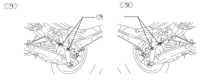
*1 for LH: *2 for RH: *3 Matchmarks -
Check adjusting tube for looseness.
-
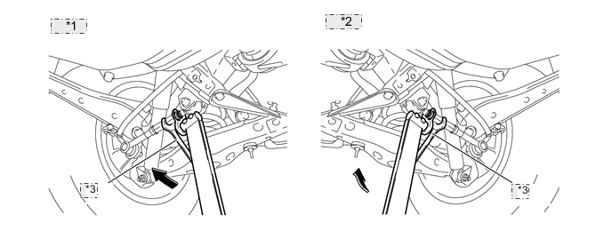
Using the SST, try turning the adjusting tube in both clockwise and counterclockwise directions with the specified torque to check that the matchmarks will not be misaligned.
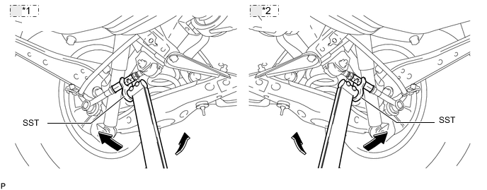
*1 for RH: *2 for LH: - SST
- 09612-24014 ( 09617-24011 )
- Torque:
- without SST
- 20 N*m { 204 kgf*cm, 15 ft.*lbf }
- with SST
- 17 N*m { 173 kgf*cm, 13 ft.*lbf }
Note
-
Do not apply more force than specified when checking for adjusting tube or lock nut looseness.
-
Use the formula to calculate special torque values for situations where SST is combined with a torque wrench Click here.
Tech Tips
Use a torque wrench with a fulcrum length of 300 mm (11.8 in.).
-
-
Check the lock nut at the ball joint side for looseness.
-
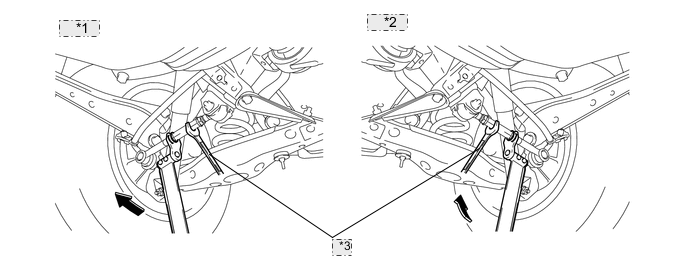
Hold the adjusting tube and using the SST, turn the lock nut at the ball joint side in both clockwise and counterclockwise directions with the specified torque to check that the matchmarks will not be misaligned.
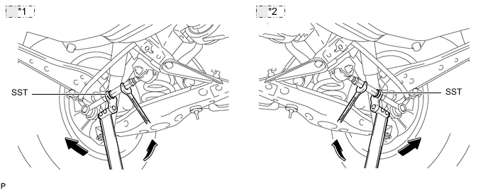
*1 for RH: *2 for LH: - SST
- 09612-24014 ( 09617-24011 )
- Torque:
- without SST
- 20 N*m { 204 kgf*cm, 15 ft.*lbf }
- with SST
- 17 N*m { 173 kgf*cm, 13 ft.*lbf }
Note
-
The wrench applied to the adjusting tube should not be turned during this step. Hold the wrench applied to the adjusting tube while applying force to the SST or torque wrench.
-
Use the formula to calculate special torque values for situations where SST is combined with a torque wrench Click here.
Tech Tips
Use a torque wrench with a fulcrum length of 300 mm (11.8 in.).
If the lock nut is found loose, replace the tie rod assembly and adjust the rear wheel alignment.
-
-
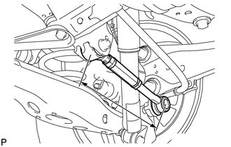
Measure the length of the left and right rear No. 1 suspension arms.
Standard difference 1.0 mm (0.0394 in.) or less -
Loosen the 2 lock nuts of the adjusting tube.
Note
If either nut is abnormally tight when loosening it (90 N*m (918 kgf*cm, 66 ft.*lbf) or more), or if either nut does not rotate smoothly by hand after loosening it, replace the rear No. 1 suspension arm.
Tech Tips
Loosen the 2 lock nuts of the adjusting tube on the other side using the same procedure.
-
If the difference between the length of the left and right rear No. 1 suspension arms is not within the specification, adjust the value to within the specification using the method below.
-
If the toe-in value deviates towards the inside, turn the adjusting tube of the shorter No. 1 suspension arm assembly in the direction which increases arm length until the difference between the left and right suspension arms is within the specification.
-
If the toe-in value deviates towards the outside, turn the adjusting tube of the longer No. 1 suspension arm assembly in the direction which decreases arm length until the difference between the left and right suspension arms is within the specification.
-
Measure the toe-in again.
-
-
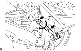
Turn the left and right adjusting tubes in the same direction by the same amount to adjust the toe-in.
Adjustment Value except Rough Road Package 1 Item Specified Condition Toe-in B - A: 1.8 +/-2 mm (0.07 +/-0.08 in.) Adjustment Value for Rough Road Package 1 Item Specified Condition Toe-in B - A: 0.3 +/-2 mm (0.01 +/-0.08 in.) Tech Tips
-
When the adjusting tube of the rear No. 1 suspension arm assembly LH is turned one revolution in the direction of A in the illustration, the toe-in changes to the inside by approximately 3.7 mm (0.146 in.).
-
When the adjusting tube of the rear No. 1 suspension arm assembly LH is turned one revolution in the direction of B in the illustration, the toe-in changes to the outside by approximately 3.7 mm (0.146 in.).
-
-
Tighten the inboard (bushing side) lock nut.
-
Hold the adjusting tube in place and using SST, tighten the lock nut on the rubber bushing side.
*1 for RH: *2 for LH: *3 Hold - SST
- 09612-24014 ( 09617-24011 )
- Torque:
- without SST
- 56 N*m { 571 kgf*cm, 41 ft.*lbf }
- with SST
- 49 N*m { 500 kgf*cm, 36 ft.*lbf }
Note
-
The wrench applied to the adjusting tube should not be turned during this step. Hold the wrench applied to the adjusting tube while applying force to the SST or torque wrench.
-
Use the formula to calculate special torque values for situations where SST is combined with a torque wrench Click here.
Tech Tips
Use a torque wrench with a fulcrum length of 300 mm (11.8 in.).
-
-
Tighten the outboard (ball joint side) lock nut.
-
Hold the adjusting tube in place and, using SST, tighten the lock nut on the ball joint side.
*1 for RH: *2 for LH: *3 Hold - SST
- 09612-24014 ( 09617-24011 )
- Torque:
- without SST
- 56 N*m { 571 kgf*cm, 41 ft.*lbf }
- with SST
- 49 N*m { 500 kgf*cm, 36 ft.*lbf }
Note
-
The wrench applied to the adjusting tube should not be turned during this step. Hold the wrench applied to the adjusting tube while applying force to the SST or torque wrench.
-
Use the formula to calculate special torque values for situations where SST is combined with a torque wrench Click here.
Tech Tips
Use a torque wrench with a fulcrum length of 300 mm (11.8 in.).
-
-
Tighten the inboard (bushing side) lock nut again.
-
Hold the adjusting tube in place and using SST, tighten the lock nut on the rubber bushing side.
*1 for RH: *2 for LH: *3 Hold - SST
- 09612-24014 ( 09617-24011 )
- Torque:
- without SST
- 56 N*m { 571 kgf*cm, 41 ft.*lbf }
- with SST
- 49 N*m { 500 kgf*cm, 36 ft.*lbf }
Note
-
Failure to follow this procedure will result in the lock nut not being tightened to the proper torque and/or becoming loose.
-
Use the formula to calculate special torque values for situations where SST is combined with a torque wrench Click here.
Tech Tips
Use a torque wrench with a fulcrum length of 300 mm (11.8 in.).
-
-
-
INSPECT CAMBER
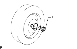
Text in Illustration *1 Gauge
-
Install a camber-caster-kingpin gauge or set the vehicle on a wheel alignment tester.
-
Inspect the camber.
Standard Camber Inclination (Unloaded Vehicle) Item Camber Inclination except Rough Road Package 1 Camber
Left-right error
-1°00' +/-45' (-1.00°+/-0.75°)
45' (0.75°) or less
for Rough Road Package 1 Camber
Left-right error
-0°48' +/-45' (-0.8°+/-0.75°)
45' (0.75°) or less
If the measured value is not within the specified range, inspect the suspension parts for damage and wear. Replace parts as necessary as the camber cannot be properly adjusted with any damaged or worn parts.
-