FRONT WHEEL ALIGNMENT ADJUSTMENT
PROCEDURE
-
INSPECT TIRES
-
Inspect the tires Click here.
-
-
MEASURE VEHICLE HEIGHT
Note
-
Before inspecting the wheel alignment, adjust the vehicle height to the specified value.
-
Be sure to perform the measurement on a level surface.
-
If it is necessary to go under the vehicle for measurement, make sure that the parking brake is applied and the vehicle is secured with chocks.
-
Bounce the vehicle up and down at the corners several times to stabilize the suspension.
-
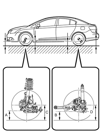
Measure the vehicle height.
Measuring points A Ground clearance of front lower suspension arm bushing set bolt center B Ground clearance of rear suspension arm No. 2 bushing set bolt center C Ground clearance of front wheel center D Ground clearance of rear wheel center Standard Vehicle Height (Unloaded Vehicle) except Rough Road Package 1 Front C - A Rear D - B 101 mm (3.98 in.) 62 mm (2.44 in.) Standard Vehicle Height (Unloaded Vehicle) for Rough Road Package 1 Front C - A Rear D - B 94 mm (3.70 in.) 46 mm (1.81 in.) Note
The standard value shown here is a value that is used for adjusting the wheel alignment and does not indicate the height of an actual vehicle.
-
-
INSPECT CAMBER, CASTER AND STEERING AXIS INCLINATION
-
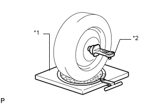
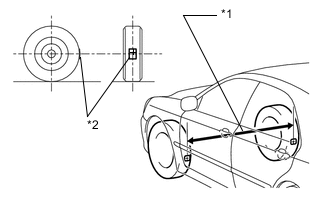
Text in Illustration *1 Alignment Tester *2 Gauge Install a camber-caster-kingpin gauge or place the front wheels on the center of a wheel alignment tester.
-
Inspect the camber, caster and steering axis inclination.
Standard Camber Inclination (Unloaded Vehicle) except Rough Road Package 1 Tire Size Camber Inclination Right-left Difference 205/60R16 -0°11' +/-45'
(-0.18° +/-0.75°)
45' (0.75°) or less 215/55R17 -0°12' +/-45'
(-0.20° +/-0.75°)
45' (0.75°) or less 225/45R18 -0°11' +/-45'
(-0.18° +/-0.75°)
45' (0.75°) or less Standard Camber Inclination (Unloaded Vehicle) for Rough Road Package 1 Camber Inclination Right-left Difference -0°9' +/-45'
(-0.15° +/-0.75°)
45' (0.75°) or less Standard Caster Inclination (Unloaded Vehicle) except Rough Road Package 1 Tire Size Caster Inclination Right-left Difference 205/60R16 5°56' +/-45'
(5.93° +/-0.75°)
45' (0.75°) or less 215/55R17 5°57' +/-45'
(5.95° +/-0.75°)
45' (0.75°) or less 225/45R18 5°58' +/-45'
(5.97° +/-0.75°)
45' (0.75°) or less Standard Caster Inclination (Unloaded Vehicle) for Rough Road Package 1 Caster Inclination Right-left Difference 5°40' +/-45'
(5.67° +/-0.75°)
45' (0.75°) or less Standard Steering Axis Inclination (Unloaded Vehicle) except Rough Road Package 1 Tire Size Steering Axis Inclination 205/60R16 13°5'
(13.08°)
215/55R17 13°5'
(13.08°)
225/45R18 13°4'
(13.07°)
Standard Steering Axis Inclination (Unloaded Vehicle) for Rough Road Package 1 Steering Axis Inclination 12°55'
(12.92°)
-
-
ADJUST CAMBER
Note
Inspect toe-in after the camber has been adjusted.
-
Remove the front wheel. *1
-
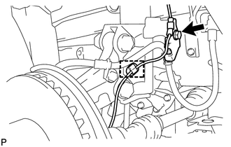
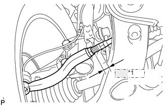
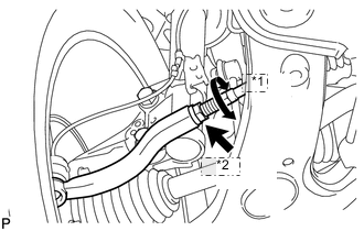
Remove the bolt, detach the clamp and disconnect the front speed sensor. *2
-
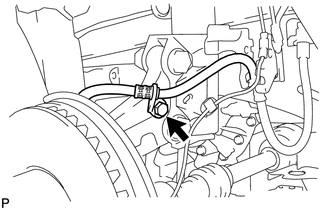
Remove the bolt and disconnect the front flexible hose. *3
-
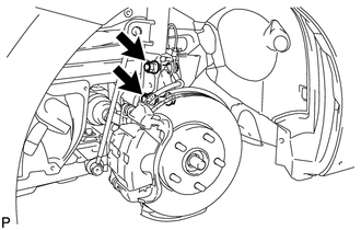
Remove the 2 nuts on the lower side of the front shock absorber.
Note
Keep the bolts inserted.
-
Clean the installation surfaces of the front shock absorber and the steering knuckle.
-
Temporarily install the 2 nuts (Step A).
-
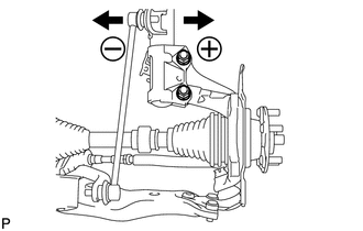
Fully push or pull the front axle hub in the direction of the required adjustment (Step B).
-
Tighten the nuts. *4
- Torque:
- 240 N*m { 2447 kgf*cm, 177 ft.*lbf }
Note
Prevent the bolts from rotating when tightening the nuts.
-
Connect the front flexible hose to the steering knuckle with the bolt. *5
- Torque:
- 29 N*m { 296 kgf*cm, 21 ft.*lbf }
-
Connect the front flexible hose and front speed sensor with the bolt. *6
- Torque:
- 29 N*m { 296 kgf*cm, 21 ft.*lbf }
Note
Do not twist the front speed sensor when installing it.
-
Attach the clamp of the front speed sensor. *7
-
Install the front wheel. *8
- Torque:
- 103 N*m { 1050 kgf*cm, 76 ft.*lbf }
-
Check the camber.
Standard Camber Inclination (Unloaded Vehicle) except Rough Road Package 1 Tire Size Camber Inclination Right-left Difference 205/60R16 -0°11' +/-45'
(-0.18° +/-0.75°)
45' (0.75°) or less 215/55R17 -0°12' +/-45'
(-0.20° +/-0.75°)
45' (0.75°) or less 225/45R18 -0°11' +/-45'
(-0.18° +/-0.75°)
45' (0.75°) or less Standard Camber Inclination (Unloaded Vehicle) for Rough Road Package 1 Camber Inclination Right-left Difference -0°9' +/-45'
(-0.15° +/-0.75°)
45' (0.75°) or less -
Perform the steps *1 to *3
If the measured value is not within the specification, calculate the required adjustment amount using the formula below.
Camber adjustment amount = center value of the specified range - measured value.
Check the combination of installed bolts. Select appropriate bolts from the table below to adjust the camber to the specified values.
Tech Tips
Try to adjust the camber to the center of the specified values.
Move Axle toward (+) in Step (B) Move Axle toward (-) in Step (B) Refer to table (1) (Move the axle toward the positive side) Refer to table (2) (Move the axle toward the negative side) 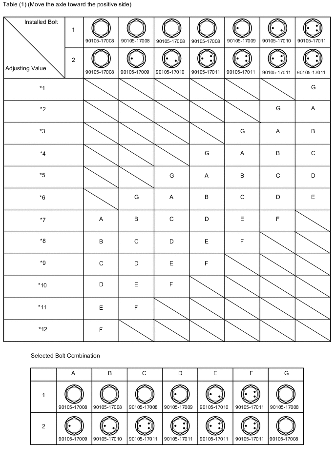
Text in Illustration *1 -1°30' to -1°15' (-1.50° to -1.25°) *2 -1°15' to -1°00' (-1.25° to -1°) *3 -1°00' to -0°45' (-1° to -0.75°) *4 -0°45' to -0°30' (-0.75° to -0.5°) *5 -0°30' to -0°15' (-0.5° to -0.25°) *6 -0°15' to 0° (-0.25° to 0°) *7 0° to 0°15' (0° to 0.25°) *8 0°15' to 0°30' (0.25° to 0.5°) *9 0°30' to 0°45' (0.5° to 0.75°) *10 0°45' to 1°00' (0.75° to 1°) *11 1°00' to 1°15' (1° to 1.25°) *12 1°15' to 1°30' (1.25° to 1.5°) 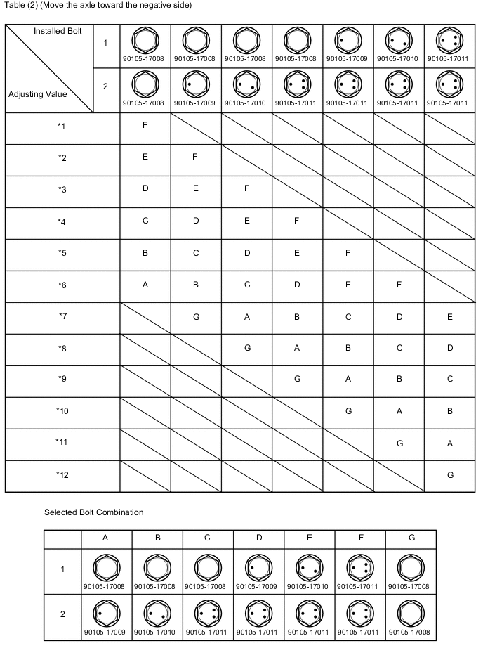
Text in Illustration *1 -1°30' to -1°15' (-1.50° to -1.25°) *2 -1°15' to -1°00' (-1.25° to -1°) *3 -1°00' to -0°45' (-1° to -0.75°) *4 -0°45' to -0°30' (-0.75° to -0.5°) *5 -0°30' to -0°15' (-0.5° to -0.25°) *6 -0°15' to 0° (-0.25° to 0°) *7 0° to 0°15' (0° to 0.25°) *8 0°15' to 0°30' (0.25° to 0.5°) *9 0°30' to 0°45' (0.5° to 0.75°) *10 0°45' to 1°00' (0.75° to 1°) *11 1°00' to 1°15' (1° to 1.25°) *12 1°15' to 1°30' (1.25° to 1.5°) Note
Replace the nut with a new one when replacing a bolt.
-
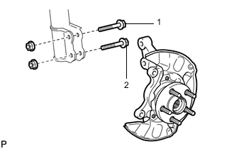
Remove the 2 nuts on the lower side of the front shock absorber.
-
Replace the adjusting bolts with the selected ones.
-
Install the 2 nut on the lower side of the front shock absorber.
-
Check the camber.
The body and suspension may be damaged if the camber is not correctly adjusted according to the table above.
-
Perform the steps *4 to *8
-
-
INSPECT TOE-IN
-
Bounce the vehicle up and down at the corners to stabilize the suspension.
-
Release the parking brake and move the shift lever to N.
-
Push the vehicle straight ahead approximately 5 m (16.4 ft.). *1
-
*1 Dimension B *2 Tread Center Mark Put tread center marks on the rearmost points of the front wheels and measure the distance between the marks (dimension B).
-
Slowly push the vehicle straight ahead to rotate the front wheels 180° using the front tire valve as a reference point.
Tech Tips
Do not allow the wheels to rotate more than 180°. If the wheels rotate more than 180°, perform the procedure from *1 again.
-
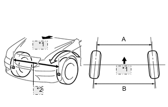
*1 Front *2 Dimension A Measure the distance between the tread center marks on the front side of the wheels (dimension A).
Toe-in except Rough Road Package 1 Item Standard Toe-in Toe-in
(total)
B - A: 2.0 +/-2.0 mm (0.08 +/-0.08 in.) for Rough Road Package 1 Item Standard Toe-in Toe-in
(total)
B - A: 1.0 +/-2.0 mm (0.04 +/-0.08 in.) Tech Tips
If toe-in is not within the specified range, adjust it at the rack ends.
-
-
ADJUST TOE-IN
-
*1 Difference Make sure that the lengths of the right and left rack ends are almost the same.
Standard difference 1.5 mm (0.06 in.) or less -
Remove the boot clips.
-
*1 Turn *2 Loosen Loosen the tie rod end lock nuts.
-
Turn the right and left rack ends by an equal amount to adjust the toe-in to the center value.
-
Tighten the tie rod end lock nuts.
- Torque:
- 74 N*m { 755 kgf*cm, 55 ft.*lbf }
-
Place the boots on the seats and install the clips.
Tech Tips
Make sure that the boots are not twisted.
-
-
INSPECT WHEEL ANGLE
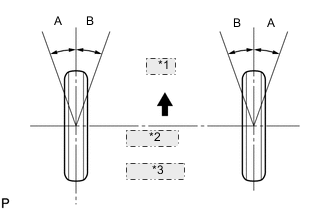
*1 Front *2 A: Inside *3 B: Outside
-
Turn the steering wheel to the left and right full lock positions, and measure the turning angle.
Standard Wheel Turning Angle (Unloaded Vehicle) except Rough Road Package 1 Tire Size Inside Wheel Outside Wheel Reference 205/60R16 38°50' +/-2°
(38.83° +/-2°)
33°11'
(33.18°)
215/55R17 38°52' +/-2°
(38.87° +/-2°)
33°11'
(33.18°)
225/45R18 38°52' +/-2°
(38.87° +/-2°)
33°12'
(33.20°)
for Rough Road Package 1 Tire Size Inside Wheel Outside Wheel Reference 205/60R16 39°12' +/-2°
(39.20° +/-2°)
33°21'
(33.35°)
215/55R17 39°2' +/-2°
(39.03° +/-2°)
33°21'
(33.35°)
-
If the angles are not as specified, check and adjust the right and left rack end lengths.
-
-