FRONT DRIVE SHAFT ASSEMBLY REASSEMBLY

PROCEDURE
-
INSTALL FRONT DRIVE SHAFT DUST COVER LH
-
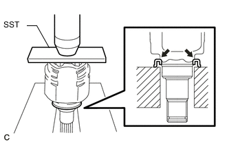
Using SST and a press, press on a new drive shaft dust cover.
- SST
- 09527-10011
Note
-
The dust cover should be installed completely.
-
Be careful not to damage the dust cover.
-
-
INSTALL FRONT DRIVE SHAFT DUST COVER RH
-
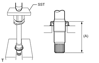
Using SST and a press, press on a new drive shaft dust cover until the dimension from the tip of the center drive shaft to the drive shaft dust cover reaches the specification as shown in the illustration.
- SST
- 09527-10011
Standard dimension (A) 115.5 to 116.5 mm (4.55 to 4.58 in.) Note
-
The dust cover should be installed completely.
-
Be careful not to damage the dust cover.
-
-
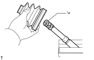
INSTALL FRONT AXLE OUTBOARD JOINT BOOT LH
Tech Tips
Before installing the boot, wrap the spline of the drive shaft with protective tape to prevent the boot from being damaged.
Text in Illustration *a Protective Tape
-
Install new parts to the outboard joint shaft in the following order.
-
No. 2 axle outboard joint boot clamp
-
Outboard joint boot
-
Outboard joint boot clamp
-
-
Pack the outboard joint shaft and boot with grease from the boot kit.
Standard Grease Capacity Engine Type Capacity for 1AD-FTV 152 to 162 g (5.36 to 5.71 oz.) for 2AD-FTV and 2AD-FHV 169 to 179 g (5.96 to 6.31 oz.)
-
-
INSTALL FRONT AXLE OUTBOARD JOINT BOOT RH
Tech Tips
Use the same procedures described for the LH side.
-
INSTALL FRONT NO. 2 AXLE OUTBOARD JOINT BOOT CLAMP LH
-
Hold the front drive shaft in a vise between aluminum plates.
Note
Do not overtighten the vise.
-
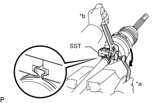
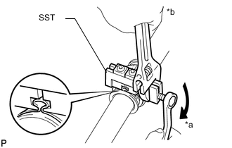
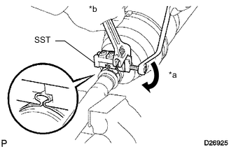
Secure the No. 2 axle outboard joint boot clamp to the boot.
-
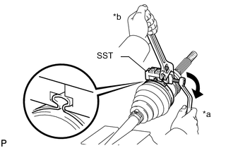
Text in Illustration *a Turn *b Hold Place SST onto the No. 2 axle outboard joint boot clamp.
- SST
- 09521-24010
-
Tighten SST so that the No. 2 axle outboard joint boot clamp is pinched.
Note
Do not overtighten SST.
-
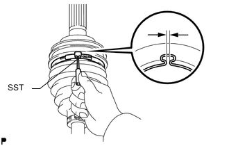
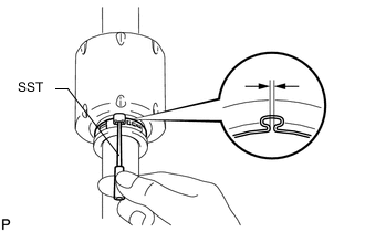
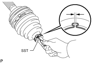
Using SST, adjust the clearance of the clamp.
- SST
- 09240-00020
Standard clearance 0.5 to 1.5 mm (0.0197 to 0.0591 in.) If the measured value exceeds the specified value, retighten the clamp.
-
-
INSTALL FRONT NO. 2 AXLE OUTBOARD JOINT BOOT CLAMP RH
Tech Tips
Use the same procedures described for the LH side.
-
INSTALL FRONT AXLE OUTBOARD JOINT BOOT CLAMP LH
-
Hold the front drive shaft in a vise between aluminum plates.
Note
Do not overtighten the vise.
-
Secure the outboard joint boot clamp to the boot.
-
Text in Illustration *a Turn *b Hold Place SST onto the outboard joint boot clamp.
- SST
- 09521-24010
-
Tighten SST so that the outboard joint boot clamp is pinched.
Note
Do not overtighten SST.
-
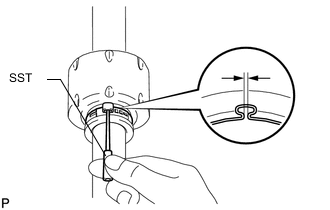
Using SST, adjust the clearance of the clamp.
- SST
- 09240-00020
Standard clearance 0.5 to 1.5 mm (0.0197 to 0.0591 in.) If the measured value exceeds the specified value, retighten the clamp.
-
-
INSTALL FRONT AXLE OUTBOARD JOINT BOOT CLAMP RH
Tech Tips
Use the same procedures described for the LH side.
-
INSTALL FRONT DRIVE SHAFT DAMPER LH
-
Install the drive shaft damper to the drive shaft.
Note
Make sure that the damper is on the shaft groove.
-
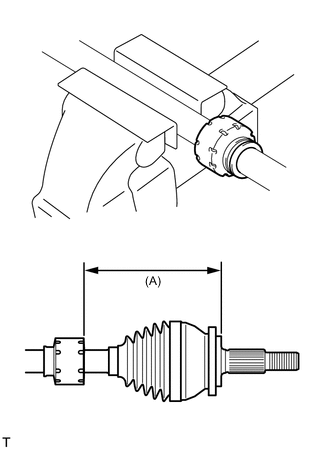
Adjust the position of the damper so that the dimension is as described below.
Standard dimension (A) 161 to 165 mm (6.34 to 6.49 in.)
-
-
INSTALL FRONT DRIVE SHAFT DAMPER CLAMP LH
-
Hold the front drive shaft in a vise between aluminum plates.
Note
Do not overtighten the vise.
-
Install a new drive shaft damper clamp to the damper.
Note
Be sure to install the clamp on the inboard joint side in the correct position.
-
Text in Illustration *a Turn *b Hold Place SST onto the damper clamp.
- SST
- 09521-24010
-
Tighten SST so that the damper clamp is pinched.
Note
Do not overtighten SST.
-
Using SST, adjust the clearance of the damper clamp.
- SST
- 09240-00020
Standard clearance 0.5 to 1.5 mm (0.0197 to 0.0591 in.) If the measured value exceeds the specified value, retighten the clamp.
-
-
INSTALL FRONT DRIVE SHAFT DAMPER RH
-
Install the drive shaft damper to the drive shaft.
Note
Make sure that the damper is on the shaft groove.
-
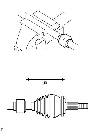
Adjust the position of the damper so that the dimension is as described below.
Standard dimension (B) 161 to 165 mm (6.34 to 6.49 in.)
-
-
INSTALL DRIVE SHAFT DAMPER SETTING CLAMP
-
Hold the front drive shaft in a vise between aluminum plates.
Note
Do not overtighten the vise.
-
Install a new drive shaft damper clamp to the damper.
Note
Be sure to install the clamp on the inboard joint side in the correct position.
-
Text in Illustration *a Turn *b Hold Place SST onto the damper clamp.
- SST
- 09521-24010
-
Tighten SST so that the damper clamp is pinched.
Note
Do not overtighten SST.
-
Using SST, adjust the clearance of the damper clamp.
- SST
- 09240-00020
Standard clearance 0.5 to 1.5 mm (0.0197 to 0.0591 in.) If the measured value exceeds the specified value, retighten the clamp.
-
-
INSTALL FRONT DRIVE INBOARD JOINT ASSEMBLY LH
-
Wrap the spline of the outboard joint shaft with protective tape to prevent the boot from being damaged.
-
Install new parts to the inboard joint shaft in the following order.
-
Inboard joint boot clamp
-
Inboard joint boot
-
No. 2 axle inboard joint boot clamp
-
-
Remove the protective tape.
-
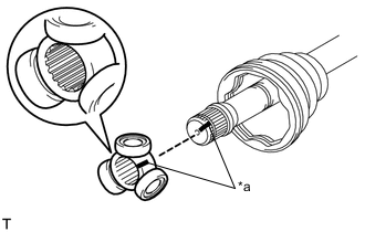
Text in Illustration *a Matchmark Place the beveled side of the tripod axial spline toward the outboard joint.
-
Align the matchmarks placed before removal.
-
Using a brass bar and hammer, tap the tripod onto the drive shaft.
Note
-
Do not tap the rollers.
-
Be sure to install the tripod in the correct direction.
-
-
Pack the inboard joint shaft and boot with grease from the boot kit.
Standard Grease Capacity Engine Type Capacity for 1AD-FTV 170 to 190 g (6.00 to 6.70 oz.) for 2AD-FTV and 2AD-FHV 140 to 160 g (4.93 to 5.64 oz.) -
Using a snap ring expander, install a new shaft snap ring.
-
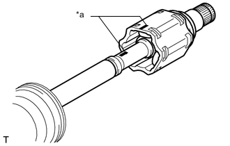
Text in Illustration *a Matchmark Align the matchmarks and install the inboard joint to the outboard joint shaft.
-
-
INSTALL FRONT DRIVE INBOARD JOINT ASSEMBLY RH
Tech Tips
Use the same procedures described for the LH side.
-
INSTALL FRONT AXLE INBOARD JOINT BOOT LH
-
Install the inboard joint boot to the inboard joint.
-
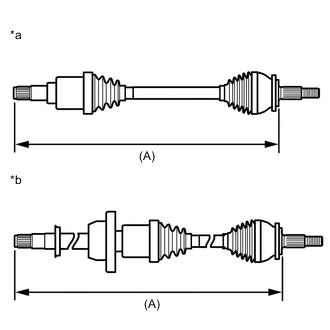
Text in Illustration *a for LH Side *b for RH Side Check that the 2 boots are not stretched or contracted when the drive shaft is at the standard length.
Dimension (A) Engine Type Item Dimension 1AD-FTV for LH side 549.8 mm (21.6 in.) for RH side 930.5 mm (36.6 in.) 2AD-FTV and 2AD-FHV for LH side 555.2 mm (21.9 in.) for RH side 929.5 mm (36.6 in.) If the boots are stretched or contracted, correct them.
-
-
INSTALL FRONT AXLE INBOARD JOINT BOOT RH
Tech Tips
Use the same procedures described for the LH side.
-
INSTALL FRONT AXLE INBOARD JOINT BOOT CLAMP LH
-
Hold the front drive shaft in a vise between aluminum plates.
Note
Do not overtighten the vise.
-
Secure the inboard joint boot clamp to the boot.
-
Text in Illustration *a Turn *b Hold Place SST onto the inboard joint boot clamp.
- SST
- 09521-24010
-
Tighten SST so that the clamp is pinched.
Note
Do not overtighten SST.
-
Using SST, adjust the clearance of the clamp.
- SST
- 09240-00020
Standard clearance 0.5 to 1.5 mm (0.0197 to 0.0591 in.) If the measured value exceeds the specified value, retighten the clamp.
-
-
INSTALL FRONT AXLE INBOARD JOINT BOOT CLAMP RH
Tech Tips
Use the same procedures described for the LH side.
-
INSTALL FRONT NO. 2 AXLE INBOARD JOINT BOOT CLAMP LH
-
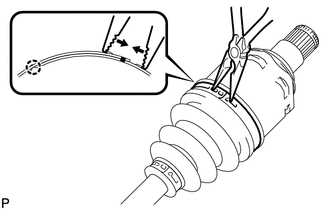
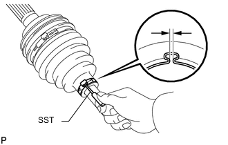
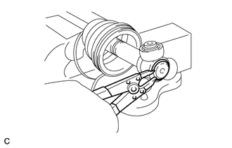
Using needle-nose pliers, install the axle inboard joint boot clamp as shown in the illustration.
Note
Be careful not to damage the boot.
-
-
INSTALL FRONT NO. 2 AXLE INBOARD JOINT BOOT CLAMP RH
Tech Tips
Use the same procedures described for the LH side.
-
INSPECT DRIVE SHAFT