DIFFERENTIAL CASE DISASSEMBLY

PROCEDURE
-
REMOVE FRONT DIFFERENTIAL CASE FRONT TAPERED ROLLER BEARING
-
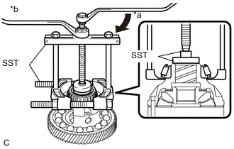
Text in Illustration *a Turn *b Hold Using SST, remove the front differential case front tapered roller bearing from the front No. 1 differential case sub-assembly.
- SST
- 09950-00020
- 09950-00030
- 09950-40011 ( 09957-04010 )
- 09950-60010 ( 09951-00560 )
-
-
REMOVE FRONT DIFFERENTIAL CASE REAR TAPERED ROLLER BEARING
-
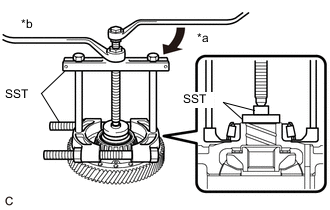
Text in Illustration *a Turn *b Hold Using SST, remove the front differential case rear tapered roller bearing from the front No. 1 differential case sub-assembly.
- SST
- 09950-00020
- 09950-00030
- 09950-40011 ( 09957-04010 )
- 09950-60010 ( 09951-00490 )
-
-
REMOVE FRONT DIFFERENTIAL RING GEAR
-
Mount the front differential ring gear in a vise between aluminum plates.
Note
-
Be careful not to damage the front differential ring gear.
-
Do not overtighten the vise.
-
-
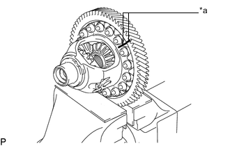
Text in Illustration *a Matchmark Put matchmarks on the front differential ring gear and front No. 1 differential case sub-assembly.
-
Remove the 16 bolts.
-
Using a plastic-faced hammer, remove the front differential ring gear from the front No. 1 differential case sub-assembly.
-
-
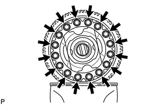
INSPECT FRONT NO. 1 DIFFERENTIAL CASE SUB-ASSEMBLY
-
REMOVE FRONT DIFFERENTIAL PINION SHAFT STRAIGHT PIN
-
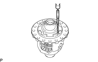
Using a 5 mm pin punch and hammer, tap out the front differential pinion shaft straight pin from the front No. 1 differential case sub-assembly.
-
-
REMOVE FRONT NO. 1 DIFFERENTIAL PINIONSHAFT
-
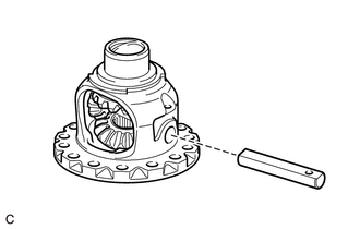
Remove the front No. 1 differential pinion shaft from the front No. 1 differential case sub-assembly.
-
-
INSPECT FRONT DIFFERENTIAL PINION BACKLASH
-
REMOVE FRONT DIFFERENTIAL SIDE GEAR
-
Set SST as shown in the illustration and tighten it.
- SST
- 09528-52010 ( 09953-05010, 09528-05010 )
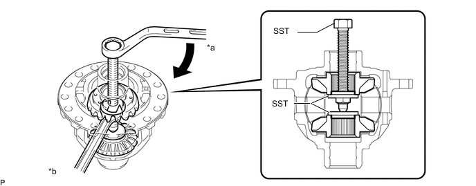
Text in Illustration *a Turn *b Hold Note
Do not overtighten SST, as doing so will damage the front differential side gear, center differential side gear conical spring washer, front No. 1 differential side gear thrust washer and front No. 1 differential case sub-assembly.
Tech Tips
-
Tighten SST until there is a clearance between the front differential pinion and front differential side gear.
-
When removing the front differential pinions, do not overtighten SST, as it is necessary to rotate the front differential side gears.
-
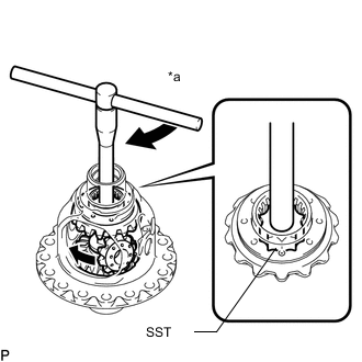
Text in Illustration *a Turn Install SST as shown in the illustration, rotate the front differential side gear, and then remove the 2 front differential pinions and 2 front differential pinion thrust washers from the front No. 1 differential case sub-assembly.
- SST
- 09528-52010 ( 09528-05030 )
Note
Do not drop the front differential pinion and front differential pinion thrust washer.
-
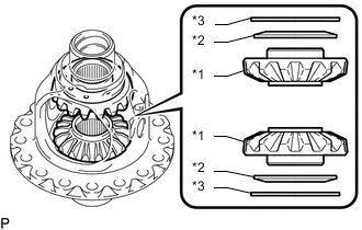
Text in Illustration *1 Front Differential Side Gear *2 Center Differential Side Gear Conical Spring Washer *3 Front No. 1 Differential Side Gear Thrust Washer Remove SST from the front No. 1 differential case sub-assembly, and then remove the 2 front differential side gears, 2 front No. 1 differential side gear thrust washers and 2 center differential side gear conical spring washers from the front No. 1 differential case sub-assembly.
Note
Do not drop the front differential side gear, front No. 1 differential side gear thrust washer and center differential side gear conical spring washer.
-