TRANSMISSION CONTROL CABLE INSTALLATION
PROCEDURE
-
INSTALL TRANSMISSION CONTROL CABLE ASSEMBLY
-
Install the control cable assembly through the floor hole.
-
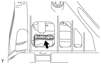
Attach the 2 claws to connect the shift control cable and select control cable to the floor shift lever assembly.
-
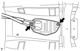
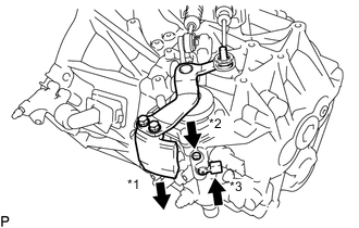
Attach the grommet of the control cable assembly with the 2 nuts.
- Torque:
- 5.0 N*m { 51 kgf*cm, 44 in.*lbf }
-
Connect the end of the shift control cable to the shift lever assembly and install the clip.
-
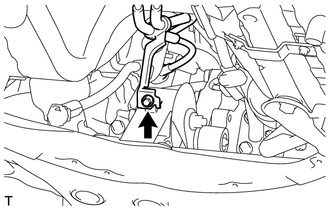
Attach the bracket of the control cable assembly with the bolt.
- Torque:
- 5.0 N*m { 51 kgf*cm, 44 in.*lbf }
-
Connect the 2 cables to the control cable bracket with 2 new clips.
-
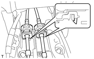
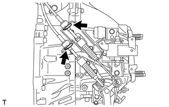
Connect the 2 cables to the transaxle and install the 2 clips.
-
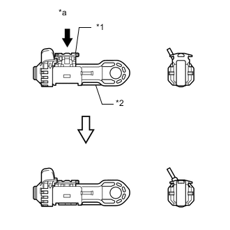
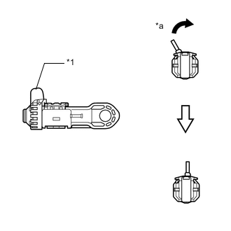
Release the lock of the cable length adjustment structure of the select cable.
-
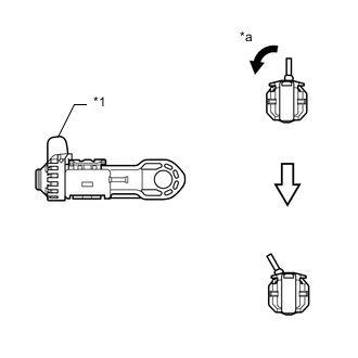
Text in Illustration *1 Stopper *a Twist Twist the stopper.
-
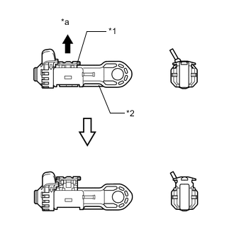
Text in Illustration *1 Lock Piece *2 Case *a Pull out Pull the lock piece outward from the case to release the lock.
-
-
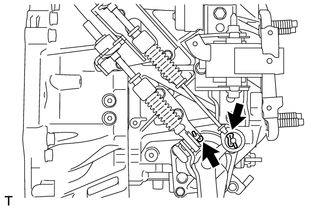
Pressing the shift and select lever shaft (*1) and pin (*2), push in pin (*3) and check that the shift and select lever shaft is secured at the 1st-2nd gear selected position (the shaft comes to a stop at the position 8 mm (0.315 in.) below the N position).
-
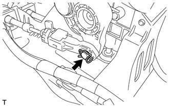
Connect the end of the select control cable to the shift lever assembly and install the clip.
Note
-
Make sure the stopper of the select control cable is facing upward when the select control cable is connected.
-
Make sure the clip is inserted in the direction shown in the illustration.
-
-
Text in Illustration *1 Slider *a Inhibitor Wall Push the slider against the inhibitor wall.
Note
-
Do not pull up the slider.
-
When adjusting the cable, make sure that the shift lever is not in 1 or 2.
-
-
Lock the cable length adjustment structure of the select cable.
-
Text in Illustration *1 Lock Piece *2 Case *a Push Push the lock piece into the case with slider held against the inhibitor wall.
-
Text in Illustration *1 Stopper *a Return Return the stopper to prevent the lock from being released.
Note
-
Push in the stopper completely.
-
Make sure the cable length adjustment structure is locked securely.
-
-
-
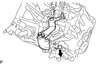
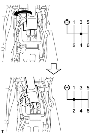
Release the pin that fixes the shift and select lever shaft.
-
Pull the pin toward the left front side of the vehicle.
Text in Illustration 
Pull
-
-
-
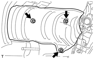
INSTALL FRONT NO. 1 FLOOR HEAT INSULATOR
-
Install the front No. 1 floor heat insulator with the 3 nuts.
- Torque:
- 5.5 N*m { 56 kgf*cm, 49 in.*lbf }
-
-
INSTALL CONSOLE BOX ASSEMBLY
w/ Console Box Lid: Click here
w/o Console Box Lid: Click here
-
CONNECT NO. 1 AIR TUBE ASSEMBLY
-
CONNECT COMPRESSOR OUTLET ELBOW
-
INSTALL NO. 4 WATER BY-PASS HOSE
-
CONNECT ENGINE WIRE
-
INSTALL AIR CLEANER CASE SUB-ASSEMBLY
-
INSTALL AIR CLEANER FILTER ELEMENT SUB-ASSEMBLY
-
INSTALL AIR CLEANER CAP SUB-ASSEMBLY WITH AIR CLEANER HOSE ASSEMBLY
-
INSTALL BATTERY CARRIER
-
INSTALL BATTERY TRAY
-
INSTALL BATTERY
-
INSTALL BATTERY INSULATOR
-
INSTALL BATTERY CLAMP SUB-ASSEMBLY
-
INSTALL FRONT EXHAUST PIPE ASSEMBLY
-
ADD ENGINE COOLANT
-
CONNECT CABLE TO POSITIVE BATTERY TERMINAL
-
INSTALL OUTER COWL TOP PANEL
-
INSTALL FRONT WIPER MOTOR AND LINK ASSEMBLY
-
CONNECT CABLE TO NEGATIVE BATTERY TERMINAL
Note
When disconnecting the cable, some systems need to be initialized after the cable is reconnected Click here.
-
INSPECT COOLANT LEAK
-
INSPECT EXHAUST GAS LEAK
-
INSTALL RADIATOR SUPPORT OPENING COVER
-
INSTALL NO. 1 ENGINE COVER
-
INSTALL NO. 1 ENGINE UNDER COVER
-
INSTALL NO. 2 ENGINE UNDER COVER