OIL COOLER INSTALLATION
PROCEDURE
-
INSTALL NO. 2 OIL COOLER TUBE SUB-ASSEMBLY
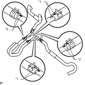
Text in Illustration *1 Yellow Paint Mark *2 Green Paint Mark *3 Blue Paint Mark
-
Install the No. 3 oil cooler outlet hose, No. 3 oil cooler inlet hose, No. 2 oil cooler outlet hose and No. 2 oil cooler inlet hose to the No. 2 oil cooler tube.
Note
Make sure the pinching portion of each clip is facing the direction shown in the illustration and the paint marks are aligned as shown in the illustration.
-
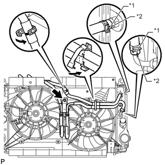
Text in Illustration *1 Yellow Paint Mark *2 White Paint Mark Install the No. 2 oil cooler tube with oil cooler hoses with the bolt.
- Torque:
- 5.5 N*m { 56 kgf*cm, 49 in.*lbf }
-
Connect the No. 3 oil cooler inlet hose and transmission oil cooler hose to the radiator.
Note
Make sure the pinching portion of each clip is facing the direction shown in the illustration and the paint marks are aligned as shown in the illustration.
-
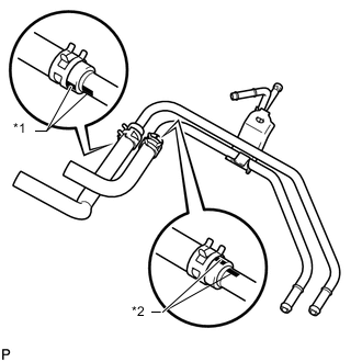
Align the 2 flexible hose clamps with the paint marks on the 2 hoses, pass the 2 hoses through the clamps and close the clamps.
-
-
INSTALL NO. 1 OIL COOLER TUBE SUB-ASSEMBLY
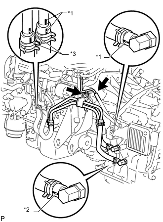
Text in Illustration *1 Yellow Paint Mark *2 White Paint Mark
-
Install the No. 1 oil cooler inlet hose and No. 1 oil cooler outlet hose to the No. 1 oil cooler tube.
Note
Make sure the pinching portion of each clip is facing the direction shown in the illustration and the paint marks are aligned as shown in the illustration.
-
Text in Illustration *1 Yellow Paint Mark *2 White Paint Mark *3 Blue Paint Mark Install the No. 1 oil cooler tube with oil cooler hoses with the bolt.
- Torque:
- 12 N*m { 117 kgf*cm, 8 ft.*lbf }
-
Connect the No. 2 oil cooler inlet hose, No. 2 oil cooler outlet hose and breather plug hose to the No. 1 oil cooler tube, and connect the No. 1 oil cooler inlet hose and No. 1 oil cooler outlet hose to the transaxle.
Note
Make sure the pinching portion of each clip is facing the direction shown in the illustration and the paint marks are aligned as shown in the illustration.
-
-
INSTALL OIL COOLER ASSEMBLY
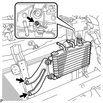
-
Install the oil cooler with the 2 bolts and nut.
- Torque:
- 5.5 N*m { 56 kgf*cm, 49 in.*lbf }
-
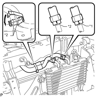
Text in Illustration *1 Blue Paint Mark *2 White Paint Mark Connect the transmission oil cooler hose and No. 3 oil cooler outlet hose to the oil cooler.
Note
Make sure the pinching portion of each clip is facing the direction shown in the illustration and the paint marks are aligned as shown in the illustration.
-
Align the 2 flexible hose clamps with the paint marks on the 2 hoses, pass the 2 hoses through the clamps and close the clamps.
-
-
INSTALL MILLIMETER WAVE RADAR SENSOR ASSEMBLY (w/ Dynamic Radar Cruise Control System)
-
Install the millimeter wave radar sensor assembly Click here.
-