VALVE BODY ASSEMBLY INSTALLATION
PROCEDURE
-
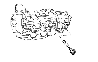
INSTALL MANUAL VALVE
-
Coat the manual valve with ATF and install it to the valve body.
-
-
INSTALL TRANSMISSION VALVE BODY ASSEMBLY
-
Coat the O-ring of the transmission wire connector with ATF.
-
Align the groove of the manual valve with the manual valve lever.
-
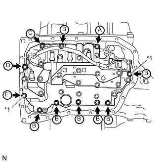
Install the valve body to the transaxle case with the 11 bolts.
Note
-
When installing the transmission valve body assembly, be careful not to allow the transmission revolution sensor and transaxle case to interfere with each other.
-
Temporarily install the bolts marked *1 in the illustration first because they are positioning bolts.
- Torque:
- 11 N*m { 110 kgf*cm, 8 ft.*lbf }
Tech Tips
Each bolt length is indicated below.
Bolt A: 25 mm (0.984 in.)
Bolt B: 30 mm (1.18 in.)
Bolt C: 35 mm (1.38 in.)
Bolt D: 45 mm (1.77 in.)
Bolt E: 55 mm (2.17 in.)
-
-
-
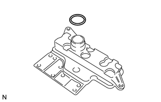
INSTALL VALVE BODY OIL STRAINER ASSEMBLY
-
Coat a new O-ring with ATF and install it to the oil strainer.
Note
Ensure that the O-ring is not twisted or pinched.
-
Install the oil strainer to the valve body with the 2 bolts.
- Torque:
- 11 N*m { 110 kgf*cm, 8 ft.*lbf }
-
-
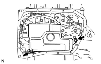
INSTALL AUTOMATIC TRANSAXLE OIL PAN SUB-ASSEMBLY
-
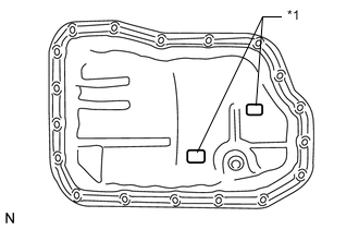
Install the 2 magnets to the oil pan.
Text in Illustration *1 Magnet -
Install a new gasket to the oil pan.
-
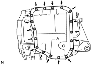
Apply seal packing to the bolt labeled A in the illustration.
Seal packing Toyota Genuine Seal Packing 1281, Three Bond 1281 or equivalent -
Install the oil pan to the automatic transaxle with the 18 bolts.
- Torque:
- for bolt labeled A
- 7.0 N*m { 71 kgf*cm, 62 in.*lbf }
- for other bolts
- 7.5 N*m { 76 kgf*cm, 66 in.*lbf }
Note
-
In order to ensure proper sealing of the transmission oil pan bolt, apply seal packing to the bolt and install it within 10 minutes of seal packing application.
-
Completely remove any oil or grease from the contact surfaces of the transaxle case, oil pan sub-assembly and gasket before installation.
-
-
INSTALL FRONT SUSPENSION MEMBER REINFORCEMENT LH
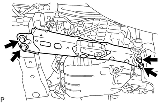
-
Install the front suspension member reinforcement with the 4 bolts.
- Torque:
- 99 N*m { 1010 kgf*cm, 73 ft.*lbf }
-
-
ADD AUTOMATIC TRANSAXLE FLUID
-
Add automatic transaxle fluid (See page AUTOMATIC TRANSMISSION / TRANSAXLE (U660E) > AUTOMATIC TRASAXLE FLUID > ADJUSTMENT).
-
-
INSTALL REAR ENGINE UNDER COVER LH
-
Install the rear engine under cover LH with the 5 clips.
-
-
INSTALL NO. 1 ENGINE UNDER COVER
-
Install the engine under cover with the 11 clips.
-
-
INSTALL FRONT LOWER BUMPER ABSORBER
-
Insert the 2 hooks of the front lower bumper absorber into the installation holes on the body to install the front lower bumper absorber.
-
Install the 8 bolts.
-
Install the 2 clips.
-