AUTOMATIC TRANSAXLE SYSTEM Pattern Select Switch Sport Mode Circuit
DESCRIPTION
The TCM memory contains the programs for the normal and sport shift patterns.
By following the programs corresponding to the signals from the pattern select switch assembly, park/neutral position switch and other various sensors, the TCM switches the shift solenoid valves on and off, and controls the transaxle gear ratio.
WIRING DIAGRAM
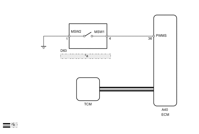
| *a | Pattern Select Switch Assembly |
| *b | CAN Communication Line |
PROCEDURE
-
INSPECT PATTERN SELECT SWITCH ASSEMBLY
-
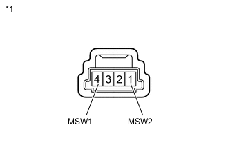
Text in Illustration *1 Component without harness connected
(Pattern Select Switch Assembly)
Remove the pattern select switch assembly Click here.
-
Measure the resistance according to the value(s) in the table below.
Standard Resistance Tester Connection Switch Condition Specified Condition 4 (MSW1) - 1 (MSW2) Pattern select switch on Below 1 Ω 4 (MSW1) - 1 (MSW2) Pattern select switch off 10 kΩ or higher
NG 
REPLACE PATTERN SELECT SWITCH ASSEMBLY Click here
OK 
-
-
CHECK HARNESS AND CONNECTOR (PATTERN SELECT SWITCH ASSEMBLY - BODY GROUND)
-
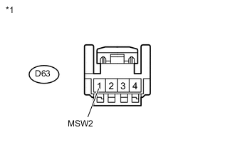
Text in Illustration *1 Front view of wire harness connector
(to Pattern Select Switch Assembly)
Disconnect the pattern select switch assembly connector.
-
Measure the resistance according to the value(s) in the table below.
Standard Resistance Tester Connection Condition Specified Condition D63-1 (MSW2) - Body ground Always Below 1 Ω
NG
REPAIR OR REPLACE HARNESS OR CONNECTOR
OK
-
-
CHECK HARNESS AND CONNECTOR (PATTERN SELECT SWITCH ASSEMBLY - ECM)
-
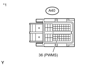
Text in Illustration *1 Front view of wire harness connector
(to ECM)
Disconnect the ECM connector.
-
Measure the resistance according to the value(s) in the table below.
Standard Resistance Tester Connection Switch Condition Specified Condition A40-36 (PWMS) - Body ground Pattern select switch on Below 1 Ω A40-36 (PWMS) - Body ground Pattern select switch off 10 kΩ or higher
OK
PROCEED TO NEXT SUSPECTED AREA SHOWN IN PROBLEM SYMPTOMS TABLE Click here
NG
REPAIR OR REPLACE HARNESS OR CONNECTOR
-