ADJUSTABLE SPEED LIMITER SWITCH(for RHD) INSPECTION
PROCEDURE
-
INSPECT WARNING CANCELING SWITCH ASSEMBLY
-
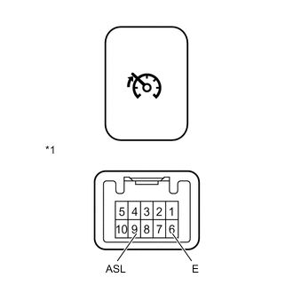
Text in Illustration *1 Component without harness connected
(Warning Canceling Switch)
Measure the resistance according to the value(s) in the table below.
Standard Resistance Tester Connection Switch Condition Specified Condition 9 (ASL) - 6 (E) Warning canceling switch on Below 1 Ω 9 (ASL) - 6 (E) Warning canceling switch off 1 MΩ or higher
-
If the result is not as specified, replace the warning canceling switch assembly.
-
-
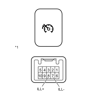
Text in Illustration *1 Component without harness connected
(Warning Canceling Switch)
Apply battery voltage to the switch connector and check the indicator (LED) illumination condition.
OK Measurement Condition Specified Condition Battery positive (+) → Terminal 8 (ILL+)
Battery negative (-) → Terminal 7 (ILL-)
Indicator (LED) illuminates If the result is not as specified, replace the warning canceling switch assembly.
-