LANE DEPARTURE ALERT SYSTEM Lane Departure Alert System Switch Circuit
DESCRIPTION
The lane departure alert system and LDA indicator (green) in the combination meter assembly turn on or off when the lane departure alert main switch of steering pad switch assembly is pressed.
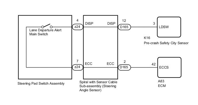
WIRING DIAGRAM
CAUTION / NOTICE / HINT
Note
-
When replacing the pre-crash safety city sensor, replace it with a new one and be sure to initialize the settings. If an ECU which was installed to another vehicle is used, the information stored in the pre-crash safety city sensor will not match the information from the vehicle and, as a result, a DTC may be output.
-
When the pre-crash safety city sensor is replaced with a new one or it is removed, camera beam axis learning must be performed.
-
The vehicle is equipped with a Supplemental Restraint System (SRS) which includes components such as airbags. Before servicing (including removal or installation of parts), be sure to read the precaution for Supplemental Restraint System Click here.
PROCEDURE
-
INSPECT STEERING PAD SWITCH ASSEMBLY
-
Remove the steering pad switch assembly Click here.
-
Inspect the steering pad switch assembly Click here.
NG 
REPLACE STEERING PAD SWITCH ASSEMBLY Click here
OK 
-
-
INSPECT SPIRAL WITH SENSOR CABLE SUB-ASSEMBLY
-
Remove the spiral with sensor cable sub-assembly Click here.
-
Inspect the spiral with sensor cable sub-assembly Click here.
NG
REPLACE SPIRAL WITH SENSOR CABLE SUB-ASSEMBLY Click here
OK
-
-
CHECK HARNESS AND CONNECTOR (SPIRAL WITH SENSOR CABLE SUB-ASSEMBLY - PRE-CRASH SAFETY CITY SENSOR)
-
Disconnect the D165 spiral with sensor cable sub-assembly connector.
-
Disconnect the K16 pre-crash safety city sensor connector.
-
Measure the resistance according to the value(s) in the table below.
Standard Resistance Tester Connection Condition Specified Condition D165-12 (DISP) - K16-3 (LDSW) Always Below 1 Ω D165-12 (DISP) or K16-3 (LDSW) - Body ground Always 10 kΩ or higher
NG
REPAIR OR REPLACE HARNESS OR CONNECTOR
OK
-
-
CHECK HARNESS AND CONNECTOR (SPIRAL WITH SENSOR CABLE SUB-ASSEMBLY - ECM)
-
Disconnect the D165 spiral with sensor cable sub-assembly connector.
-
Disconnect the A83 ECM connector.
-
Measure the resistance according to the value(s) in the table below.
Standard Resistance Tester Connection Condition Specified Condition D165-2 (ECC) - A83-42 (ECCS) Always Below 1 Ω D165-2 (ECC) or A83-42 (ECCS) - Body ground Always 10 kΩ or higher
OK
PROCEED TO NEXT SUSPECTED AREA SHOWN IN PROBLEM SYMPTOMS TABLE Click here
NG
REPAIR OR REPLACE HARNESS OR CONNECTOR
-