RADIATOR(for Manual Transaxle) INSTALLATION
PROCEDURE
-
INSTALL FAN SHROUD
-
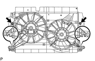
Insert the fan shroud hooks into the radiator holes and install the fan shroud with the 2 bolts.
- Torque:
- 7.0 N*m { 71 kgf*cm, 62 in.*lbf }
-
-
INSTALL INTERCOOLER ASSEMBLY
-
INSTALL LOWER RADIATOR SUPPORT SUB-ASSEMBLY
-
INSTALL NO. 3 VACUUM TRANSMITTING PIPE SUB-ASSEMBLY (for Manual Transaxle)
-
Attach the clamp to the lower radiator support.
-
Install the No. 3 vacuum transmitting pipe with the 3 bolts.
- Torque:
- 7.0 N*m { 71 kgf*cm, 62 in.*lbf }
-
-
INSTALL NO. 2 AIR TUBE
-
Install the No. 2 air tube with the bolt.
Note
Before installation, remove any oil residue from the inside of the pipe and hose.
- Torque:
- 31 N*m { 316 kgf*cm, 23 ft.*lbf }
-
Tighten the hose clamp.
- Torque:
- 6.5 N*m { 66 kgf*cm, 58 in.*lbf }
-
Connect the air temperature sensor connector.
-
-
INSTALL RADIATOR ASSEMBLY
-
Install the 2 radiator lower support cushions.
-
Insert the radiator with intercooler while holding it at an angle to install it as shown in the illustration.
Note
w/ Air Conditioning System:
Do not apply any excessive force to the cooler pipe when installing the radiator assembly.
-
Connect the No. 2 vacuum transmitting hose.
-
-
INSTALL CONDENSER ASSEMBLY WITH RECEIVER (w/ Air Conditioning System)
-
INSTALL HOOD LOCK SUPPORT SUB-ASSEMBLY
-
Install the radiator support with the 4 bolts.
- Torque:
- 13 N*m { 127 kgf*cm, 9 ft.*lbf }
-
-
INSTALL HOOD LOCK ASSEMBLY
-
Install the hood lock with the 3 bolts.
- Torque:
- 7.5 N*m { 76 kgf*cm, 66 in.*lbf }
-
Connect the hood lock control cable.
-
w/ Engine Hood Courtesy Switch:
Attach the clamp and connect the hood lock courtesy switch connector.
-
-
INSTALL UPPER RADIATOR SUPPORT SUB-ASSEMBLY
-
Install the 2 upper radiator supports with the 4 bolts.
- Torque:
- 7.0 N*m { 71 kgf*cm, 62 in.*lbf }
-
Install the 2 radiator support cushions.
-
-
INSTALL UPPER RADIATOR SUPPORT
-
Install the 2 upper radiator supports with the 2 bolts.
- Torque:
- 19 N*m { 194 kgf*cm, 14 ft.*lbf }
-
-
CONNECT SUCTION PIPE SUB-ASSEMBLY (w/ Air Conditioning System)
-
CONNECT DISCHARGE HOSE SUB-ASSEMBLY (w/ Air Conditioning System)
-
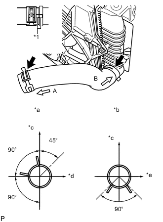
INSTALL NO. 3 AIR HOSE
Note
Before installation, remove any oil residue from the inside of the throttle body and tube.
-
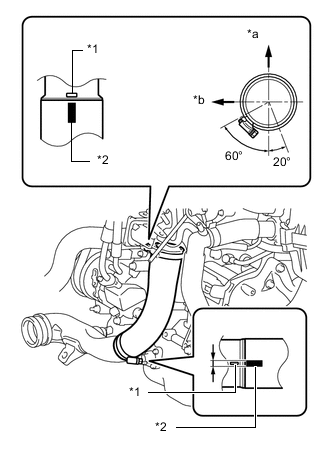
Text in Illustration *1 Embossed Mark *2 Paint Mark *a Rear *b RH Side Align the paint mark of the No. 3 air hose with the embossed mark of the throttle body.
-
Align the paint mark of the No. 3 air hose with the embossed mark of the No. 2 air tube.
-
Tighten the clamp of the No. 3 air hose on the diesel throttle body side.
- Torque:
- 6.5 N*m { 66 kgf*cm, 58 in.*lbf }
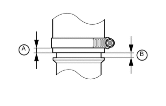
Tech Tips
-
Align the paint mark of the air hose with the embossed mark and push in the air hose so that distance B is 0 to 2 mm (0 to 0.0787 in.).
-
Position the clamp so that distance A is 4 to 9 mm (0.157 to 0.354 in.).
-
Tighten the clamp of the No. 3 air hose on the No. 2 air tube side.
- Torque:
- 6.5 N*m { 66 kgf*cm, 58 in.*lbf }
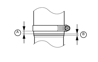
Tech Tips
-
Align the paint mark of the air hose with the embossed mark and push in the air hose so that distance B is 0 to 2 mm (0 to 0.0787 in.).
-
Position the clamp so that distance A is 9 to 15 mm (0.354 to 0.591 in.).
-
-
INSTALL INTERCOOLER AIR HOSE
Note
-
Check that the retainer is closed when the connector is inserted.
-
If replacing the hose, check for deposits in the intercooler and intercooler air hose. If necessary, wipe up deposits.
-
If replacing the hose, apply fresh oil to the O-ring.
-
Push on the connector until it makes a click sound which indicates that the connection is complete. After connecting the connector, check that the connector cannot be disconnected by pulling the connector.
-
Do not use a quick connector that has been dropped.
-
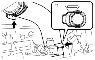
Text in Illustration *1 Retainer Install the intercooler air hose to the intercooler and No. 1 air tube and push in the retainer.
-
Tighten the hose clamp.
- Torque:
- 6.5 N*m { 66 kgf*cm, 58 in.*lbf }
-
-
INSTALL NO. 2 RADIATOR HOSE
-
Text in Illustration *1 Match Mark *a View A *b View B *c Top *d LH Side *e RH Side Connect the No. 2 radiator hose.
Tech Tips
Position the clips as illustrated.
-
-
INSTALL NO. 1 RADIATOR HOSE
-
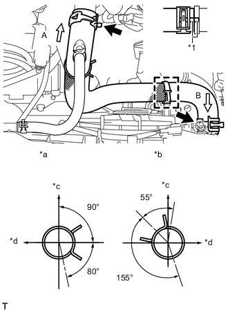
Text in Illustration *1 Match Mark *a View A *b View B *c Top *d RH Side Connect the No. 1 radiator hose.
Tech Tips
Position clips A and B as Illustrated.
-
-
INSTALL INJECTOR DRIVER
-
CONNECT NO. 1 WATER HOSE CLAMP BRACKET
-
Connect the No. 1 water hose clamp bracket to the radiator support with the 2 bolts.
- Torque:
- 5.0 N*m { 51 kgf*cm, 44 in.*lbf }
-
Attach the 2 hose clamps to the No. 2 by-pass water hose, and then connect the No. 1 radiator hose to the No. 1 water hose clamp bracket.
-
-
INSTALL NO. 3 WATER BY-PASS HOSE
-
Connect the 3 connectors and attach the clamp.
-
Install the No. 3 water by-pass hose and attach the clamp.
-
-
INSTALL RADIATOR SIDE DEFLECTOR LH
-
INSTALL RADIATOR SIDE DEFLECTOR RH
-
INSTALL RADIATOR GRILLE BRACKET
-
Install the radiator grille bracket with the 2 bolts and nut.
- Torque:
- 13 N*m { 127 kgf*cm, 9 ft.*lbf }
-
-
INSTALL HORN ASSEMBLY
-
Install the horn with the bolt.
- Torque:
- 20 N*m { 199 kgf*cm, 14 ft.*lbf }
-
Connect the 2 horn connectors.
-
-
CONNECT AMBIENT THERMISTOR ASSEMBLY
-
Attach the clamp to connect the ambient thermistor.
-
-
INSTALL BATTERY CARRIER
-
INSTALL BATTERY TRAY
-
INSTALL BATTERY
-
INSTALL BATTERY CLAMP SUB-ASSEMBLY
-
CONNECT CABLE TO POSITIVE BATTERY TERMINAL
-
CONNECT CABLE TO NEGATIVE BATTERY TERMINAL
Note
When disconnecting the cable, some systems need to be initialized after the cable is reconnected Click here.
-
ADD ENGINE COOLANT
-
CHARGE REFRIGERANT (w/ Air Conditioning System)
-
WARM UP ENGINE (w/ Air Conditioning System)
-
INSPECT FOR REFRIGERANT LEAK (w/ Air Conditioning System)
-
INSPECT FOR COOLANT LEAK
-
INSTALL RADIATOR SUPPORT OPENING COVER
-
Install the radiator support opening cover with the 7 clips.
-
-
INSTALL NO. 1 ENGINE COVER
-
INSTALL ENGINE UNDER COVER
-
Install the engine under cover with the 11 clips.
-
-
INSTALL FRONT LOWER BUMPER ABSORBER
-
Insert the 2 hooks of the front lower bumper absorber into the installation holes on the body to install the front lower bumper absorber.
-
Install 8 bolts and 3 screws.
-
Install the 4 screws and 2 bolts.
-