RADIATOR(for Automatic Transaxle) INSTALLATION
PROCEDURE
-
INSTALL FAN SHROUD
-
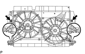
Insert the fan shroud hooks into the radiator holes and install the fan shroud with the 2 bolts.
- Torque:
- 7.0 N*m { 71 kgf*cm, 62 in.*lbf }
-
-
INSTALL INTERCOOLER ASSEMBLY (for Automatic Transaxle)
-
INSTALL LOWER RADIATOR SUPPORT SUB-ASSEMBLY
-
INSTALL NO. 3 VACUUM TRANSMITTING PIPE SUB-ASSEMBLY (for Automatic Transaxle)
-
Attach the clamp to the lower radiator support.
-
Install the No. 3 vacuum transmitting pipe with the 3 bolts.
- Torque:
- 7.0 N*m { 71 kgf*cm, 62 in.*lbf }
-
-
INSTALL OIL COOLER HOSE TUBE SUB-ASSEMBLY
-
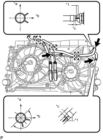
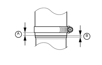
Text in Illustration *1 Paint Mark *a Top *b RH Side *c 2 to 7 mm (0.0787 to 0.275 in.) Connect the 2 hoses of the oil cooler hose tube to the radiator and attach the 2 clips.
Tech Tips
-
Position the clips and align the paint marks as illustrated.
-
Position the clips so that the distance from the end of the hose is 2 to 7 mm (0.0787 to 0.275 in.).
-
-
Attach the 3 clamps and install the oil cooler hose tube with the bolt.
- Torque:
- 5.5 N*m { 56 kgf*cm, 49 in.*lbf }
-
-
INSTALL NO. 2 AIR TUBE
-
Install the No. 2 air tube with the bolt.
Note
Before installation, remove any oil residue from the inside of the pipe and hose.
- Torque:
- 31 N*m { 316 kgf*cm, 23 ft.*lbf }
-
Tighten the hose clamp.
- Torque:
- 6.5 N*m { 66 kgf*cm, 58 in.*lbf }
-
Connect the air temperature sensor connector.
-
-
INSTALL RADIATOR ASSEMBLY
-
Install the 2 radiator lower support cushions.
-
Insert the radiator with intercooler while holding it at an angle to install it as shown in the illustration.
Note
Do not apply any excessive force to the cooler pipe when installing the radiator assembly.
-
Connect the No. 2 vacuum transmitting hose.
-
Connect the 2 oil cooler hoses and attach the 2 clips.
-
-
INSTALL NO. 3 AIR HOSE
Note
Before installation, remove any oil residue from the inside of the throttle body and tube.
-
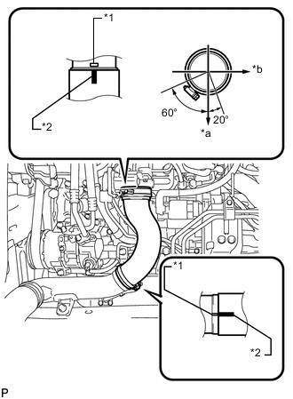
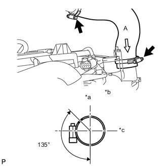
Text in Illustration *1 Embossed Mark *2 Paint Mark *a Front *b LH Side Align the paint mark of the No. 3 air hose with the embossed mark of the throttle body.
-
Align the paint mark of the No. 3 air hose with the embossed mark of the No. 2 air tube.
-
Tighten the clamp of the No. 3 air hose on the diesel throttle body side.
- Torque:
- 6.5 N*m { 66 kgf*cm, 58 in.*lbf }
Tech Tips
-
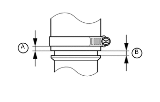
Align the paint mark of the air hose with the embossed mark and push in the air hose so that distance B is 0 to 2 mm (0 to 0.0787 in.).
-
Position the clamp so that distance A is 4 to 9 mm (0.157 to 0.354 in.).
-
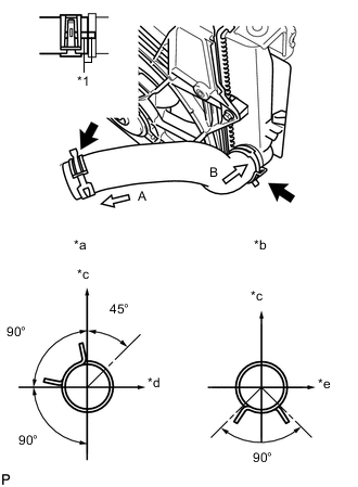
Tighten the clamp of the No. 3 air hose on the No. 2 air tube side.
- Torque:
- 6.5 N*m { 66 kgf*cm, 58 in.*lbf }
Tech Tips
-
Align the paint mark of the air hose with the embossed mark and push in the air hose so that distance B is 0 to 2 mm (0 to 0.0787 in.).
-
Position the clamp so that distance A is 9 to 15 mm (0.354 to 0.591 in.).
-
-
INSTALL INTERCOOLER AIR HOSE
Note
Before installation, remove any oil residue from the inside of the tube.
-
Text in Illustration *a Top *b View A *b RH Side Install the intercooler air hose to the No. 1 air tube and intercooler and tighten the hose clamps.
- Torque:
- 6.5 N*m { 66 kgf*cm, 58 in.*lbf }
-
Install the wire harness clamp with the bolt.
- Torque:
- 8.4 N*m { 85 kgf*cm, 74 in.*lbf }
-
Attach the clamp.
-
-
INSTALL NO. 2 RADIATOR HOSE
-
Text in Illustration *1 Match Mark *a View A *b View B *c Top *d LH Side *e RH Side Connect the No. 2 radiator hose.
Tech Tips
Position the clips as illustrated.
-
-
INSTALL NO. 1 RADIATOR HOSE
-
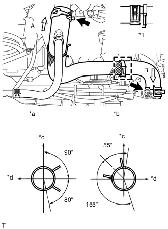
Text in Illustration *1 Match Mark *a View A *b View B *c Top *d RH Side Connect the No. 1 radiator hose.
Tech Tips
Position clips A and B as Illustrated.
-
-
INSTALL HOOD LOCK SUPPORT SUB-ASSEMBLY
-
Install the hood lock support sub-assembly with the 4 bolts.
- Torque:
- 13 N*m { 127 kgf*cm, 9 ft.*lbf }
-
-
INSTALL HOOD LOCK ASSEMBLY
-
Install the hood lock with the 3 bolts.
- Torque:
- 7.5 N*m { 76 kgf*cm, 66 in.*lbf }
-
Connect the hood lock control cable.
-
w/ Engine Hood Courtesy Switch:
Attach the clamp and connect the hood lock courtesy switch connector.
-
-
INSTALL INJECTOR DRIVER
-
CONNECT NO. 1 WATER HOSE CLAMP BRACKET
-
Connect the No. 1 water hose clamp bracket to the radiator support with the 2 bolts.
- Torque:
- 5.0 N*m { 51 kgf*cm, 44 in.*lbf }
-
Attach the 2 hose clamps to the No. 2 by-pass water hose, and then connect the No. 1 radiator hose to the No. 1 water hose clamp bracket.
-
-
INSTALL NO. 3 WATER BY-PASS HOSE
-
Connect the 3 connectors and attach the clamp.
-
Install the No. 3 water by-pass hose and attach the clamp.
-
-
INSTALL CONDENSER ASSEMBLY WITH RECEIVER
-
CONNECT SUCTION PIPE SUB-ASSEMBLY
-
CONNECT DISCHARGE HOSE SUB-ASSEMBLY
-
INSTALL UPPER RADIATOR SUPPORT SUB-ASSEMBLY
-
Install the 2 upper radiator supports with the 4 bolts.
- Torque:
- 7.0 N*m { 71 kgf*cm, 62 in.*lbf }
-
Install the 2 radiator support cushions.
-
-
INSTALL UPPER RADIATOR SUPPORT
-
Install the 2 upper radiator supports with the 2 bolts.
- Torque:
- 19 N*m { 194 kgf*cm, 14 ft.*lbf }
-
-
INSTALL RADIATOR SIDE DEFLECTOR LH
-
Install the radiator side deflector LH.
-
-
INSTALL RADIATOR SIDE DEFLECTOR RH
-
Install the radiator side deflector RH.
-
-
CONNECT AMBIENT THERMISTOR ASSEMBLY
-
Attach the clamp to connect the ambient thermistor.
-
-
INSTALL HORN ASSEMBLY
-
Install the horn with the bolt.
- Torque:
- 20 N*m { 199 kgf*cm, 14 ft.*lbf }
-
Connect the 2 horn connectors.
-
-
INSTALL RADIATOR GRILLE BRACKET
-
Install the radiator grille bracket with the bolt and nut.
- Torque:
- 13 N*m { 127 kgf*cm, 9 ft.*lbf }
-
-
INSTALL OIL COOLER ASSEMBLY
-
Install the oil cooler with the 2 bolts and nut.
- Torque:
- 5.5 N*m { 56 kgf*cm, 49 in.*lbf }
-
Connect the 2 oil cooler hoses and attach the 2 clips.
-
-
INSTALL NO. 1 MILLIMETER WAVE RADAR SENSOR BRACKET (w/ Dynamic Radar Cruise Control System)
-
INSTALL MILLIMETER WAVE RADAR SENSOR ASSEMBLY (w/ Dynamic Radar Cruise Control System)
-
INSTALL BATTERY CARRIER
-
INSTALL BATTERY TRAY
-
INSTALL BATTERY
-
INSTALL BATTERY INSULATOR
-
INSTALL BATTERY CLAMP SUB-ASSEMBLY
-
CONNECT CABLE TO POSITIVE BATTERY TERMINAL
-
CONNECT CABLE TO NEGATIVE BATTERY TERMINAL
Note
When disconnecting the cable, some systems need to be initialized after the cable is reconnected Click here.
-
ADD ENGINE COOLANT
-
CHARGE REFRIGERANT
-
WARM UP ENGINE
-
INSPECT FOR REFRIGERANT LEAK
-
ADJUSTMENT AUTOMATIC TRANSAXLE FLUID
-
Adjustment automatic transaxle fluid Click here.
-
-
INSPECT FOR COOLANT LEAK
-
ADJUST MILLIMETER WAVE RADAR SENSOR ASSEMBLY (w/ Dynamic Radar Cruise Control System)
-
INSTALL NO. 1 ENGINE COVER
-
INSTALL ENGINE UNDER COVER
-
Install the engine under cover with the 11 clips.
-
-
INSTALL FRONT LOWER BUMPER ABSORBER
-
Insert the 2 hooks of the front lower bumper absorber into the installation holes on the body to install the front lower bumper absorber.
-
Install the 8 bolts.
-
Install the 2 clips.
-
-
INSTALL FRONT BUMPER COVER
-
INSTALL RADIATOR SUPPORT OPENING COVER
-
Install the radiator support opening cover with the 7 clips.
-