INTAKE SYSTEM SYSTEM DIAGRAM

-
TURBOCHARGER SYSTEM ILLUSTRATION (for CCo)
-
The ECM calculates an optimal turbo pressure in accordance with the driving conditions (engine speed, injection volume, atmospheric pressure and engine coolant temperature). It controls the variable nozzle so that the turbo pressure detected by the turbo pressure sensor matches the calculated turbo pressure.
-
The turbo pressure (intake manifold pressure) is controlled by the variable nozzle vanes located in the turbine area. This nozzle is actuated by the actuator that is directly connected to it. This actuator is actuated by the vacuum pressure that is regulated by the vacuum regulating valve in accordance with signals from the ECM.
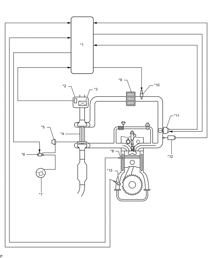
Text in Illustration *1 ECM *2 Mass Air Flow Meter *3 Air Cleaner *4 Turbocharger *5 Turbocharger Actuator *6 Vacuum Regulating Valve *7 Vacuum Pump *8 Engine Coolant Temperature Sensor *9 Intercooler *10 Intake Air Temperature Sensor *11 Diesel Throttle Body *12 Diesel Turbo Pressure Sensor *13 Crankshaft Position Sensor - - -
-
TURBOCHARGER SYSTEM ILLUSTRATION (for DPF)
-
The turbocharger system is comprised of the Variable Nozzle (VN) type turbocharger and ECM.
-
The turbocharger has a nozzle vane which opens and closes to control the volume of the exhaust gas flowing to the turbine. This, in turn, controls the boost pressure. When the nozzle vane moves in the closing direction, the pressure increases. When the vane moves in the opening direction, the pressure decreases.
-
The turbocharger actuator built onto the compressor housing side actuates the nozzle vane. The nozzle vane position sensor built onto the actuator detects the opening angle of the nozzle vane. The ECM receives a nozzle vane position sensor signal. Based on this signal, the ECM operates the DC motor and controls the nozzle vane opening angle.
-
The ECM controls the nozzle vane position according to the driving conditions in order to create the optimal pressure.
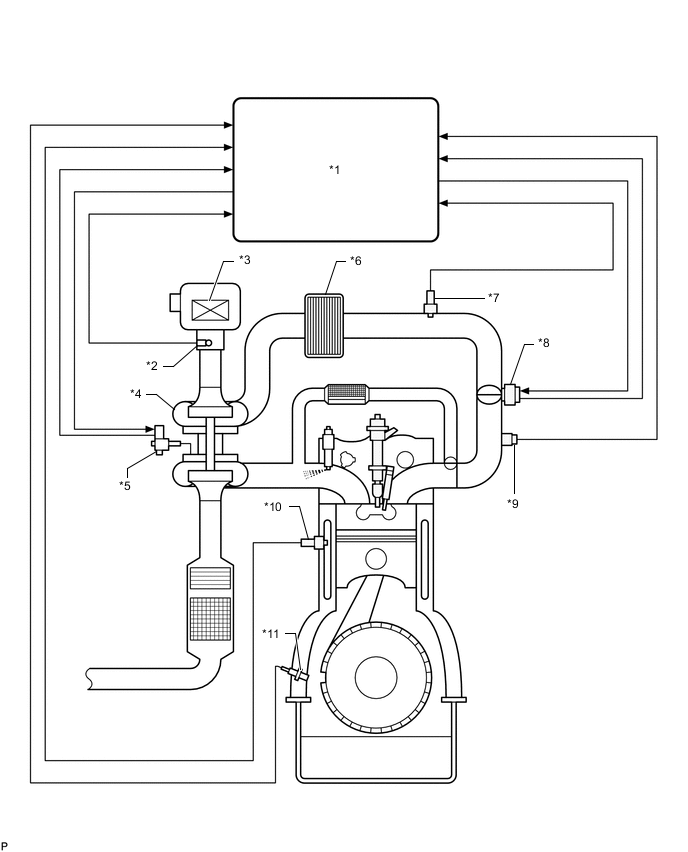
Text in Illustration *1 ECM *2 Mass Air Flow Meter *3 Air Cleaner *4 Turbocharger *5 Turbocharger Actuator
- Turbocharger Variable Nozzle Motor
- Turbocharger Variable Nozzle Sensor
*6 Intercooler *7 Intake Air Temperature Sensor *8 Diesel Throttle Body *9 Diesel Turbo Pressure Sensor *10 Engine Coolant Temperature Sensor *11 Crankshaft Position Sensor - - -
-
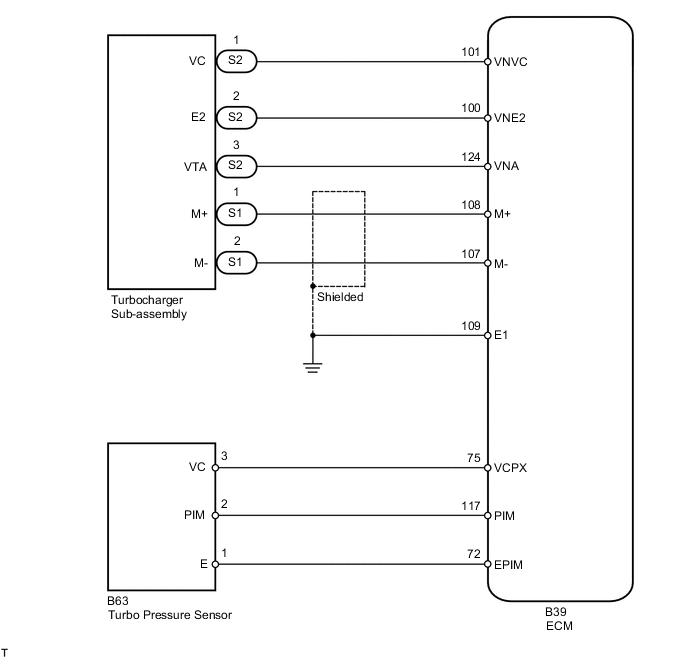
TURBOCHARGER SYSTEM WIRING DIAGRAM (for DPF)