AUDIO AND VISUAL SYSTEM(for Radio and Display Type) Reverse Signal Circuit
DESCRIPTION
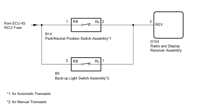
The radio and display receiver assembly receives a reverse signal from the park/neutral position switch assembly to use for adjusting the vehicle position on the multi-display.
WIRING DIAGRAM
CAUTION / NOTICE / HINT
Note
Inspect the fuses for circuits related to this system before performing the following inspection procedure.
PROCEDURE
-
CHECK VEHICLE SIGNAL (OPERATION CHECK)
-
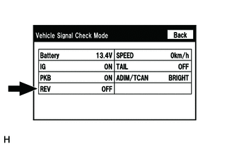
Enter the "Vehicle Signal Check Mode" screen. [Refer to Check Vehicle Signal Check Mode in Operation Check Click here]
-
Check that the display changes between ON and OFF according to the shift lever position.
OK Shift Lever Position Display R ON Except R OFF Tech Tips
This display is updated once per second. As a result, it is normal for the display to lag behind the actual shift lever position.
OK 
PROCEED TO NEXT SUSPECTED AREA SHOWN IN PROBLEM SYMPTOMS TABLE Click here
NG 
-
-
CHECK RADIO AND DISPLAY RECEIVER ASSEMBLY
-
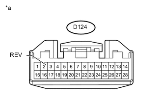
Text in Illustration *a Front view of wire harness connector
(to Radio and Display Receiver Assembly)
Disconnect the radio and display receiver assembly connector.
-
Measure the voltage according to the value(s) in the table below.
Standard Voltage Tester Connection Switch Condition Specified Condition D124-2 (REV) - Body ground Ignition switch ON, shift lever in R 7.5 to 14 V D124-2 (REV) - Body ground Ignition switch ON, shift lever not in R Below 1 V Result Result Proceed to OK A NG (for Automatic Transaxle) B NG (for Manual Transaxle) C
A
REPLACE RADIO AND DISPLAY RECEIVER ASSEMBLY Click here
C 
CHECK HARNESS AND CONNECTOR (RADIO AND DISPLAY RECEIVER ASSEMBLY - BACK-UP LIGHT SWITCH ASSEMBLY) Click here
B
-
-
CHECK HARNESS AND CONNECTOR (RADIO AND DISPLAY RECEIVER ASSEMBLY - PARK/NEUTRAL POSITION SWITCH ASSEMBLY)
-
Disconnect the D124 radio and display receiver assembly connector.
-
Disconnect the B14 park/neutral position switch assembly connector.
-
Measure the resistance according to the value(s) in the table below.
Standard Resistance Tester Connection Condition Specified Condition D124-2 (REV) - B14-2 (RL) Always Below 1 Ω D124-2 (REV) - Body ground Always 10 kΩ or higher
NG
REPAIR OR REPLACE HARNESS OR CONNECTOR
OK
-
-
CHECK HARNESS AND CONNECTOR (PARK/NEUTRAL POSITION SWITCH ASSEMBLY - BATTERY)
-
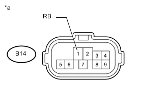
Text in Illustration *a Front view of wire harness connector
(to Park/neutral Position Switch Assembly)
Disconnect the park/neutral position switch assembly connector.
-
Measure the voltage according to the value(s) in the table below.
Standard Voltage Tester Connection Switch Condition Specified Condition B14-1 (RB) - Body ground Ignition switch ON 11 to 14 V
OK
REPLACE PARK/NEUTRAL POSITION SWITCH ASSEMBLY Click here
NG
REPAIR OR REPLACE HARNESS OR CONNECTOR
-
-
CHECK HARNESS AND CONNECTOR (RADIO AND DISPLAY RECEIVER ASSEMBLY - BACK-UP LIGHT SWITCH ASSEMBLY)
-
Disconnect the D124 radio and display receiver assembly connector.
-
Disconnect the B5 back-up light switch assembly connector.
-
Measure the resistance according to the value(s) in the table below.
Standard Resistance Tester Connection Condition Specified Condition D124-2 (REV) - B5-1 (RL) Always Below 1 Ω D124-2 (REV) - Body ground Always 10 kΩ or higher
NG
REPAIR OR REPLACE HARNESS OR CONNECTOR
OK
-
-
CHECK HARNESS AND CONNECTOR (BACK-UP LIGHT SWITCH ASSEMBLY - BATTERY)
-
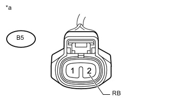
Text in Illustration *a Front view of wire harness connector
(to Back-up Light Switch Assembly)
Disconnect the back-up light switch assembly connector.
-
Measure the voltage according to the value(s) in the table below.
Standard Voltage Tester Connection Switch Condition Specified Condition B5-2 (RB) - Body ground Ignition switch ON 11 to 14 V Result Result Proceed to OK (for Manual Transaxle [EA62]) A OK (for Manual Transaxle [EA63]) B OK (for Manual Transaxle [EA65]) C NG D
A
REPLACE BACK-UP LIGHT SWITCH ASSEMBLY Click here
B
REPLACE BACK-UP LIGHT SWITCH ASSEMBLY Click here
C
REPLACE BACK-UP LIGHT SWITCH ASSEMBLY Click here
D
REPAIR OR REPLACE HARNESS OR CONNECTOR
-