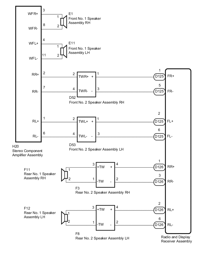
AUDIO AND VISUAL SYSTEM(for Radio and Display Type) Speaker Circuit (Independent Amplifier)
DESCRIPTION
The radio and display receiver assembly and stereo component amplifier assembly send sound signals to the speakers.
WIRING DIAGRAM
PROCEDURE
-
CHECK SPEAKER
-
Check the malfunctioning speakers.
Result Result Proceed to Malfunction in front speaker area A Malfunction in rear speaker area B
B 
CHECK SPEAKER Click here
A 
-
-
CHECK SPEAKER
-
Check the malfunctioning speakers.
Result Result Proceed to Front No. 1 speaker assembly A Front No. 2 speaker assembly B
B
CHECK HARNESS AND CONNECTOR (RADIO AND DISPLAY RECEIVER ASSEMBLY - FRONT NO. 2 SPEAKER ASSEMBLY) Click here
A
-
-
INSPECT FRONT NO. 1 SPEAKER ASSEMBLY
-
Remove the front No. 1 speaker assembly Click here.
-
Inspect the front No. 1 speaker assembly Click here.
NG 
REPLACE FRONT NO. 1 SPEAKER ASSEMBLY Click here
OK
-
-
CHECK HARNESS AND CONNECTOR (STEREO COMPONENT AMPLIFIER ASSEMBLY - FRONT NO. 1 SPEAKER ASSEMBLY)
-
Disconnect the H20 stereo component amplifier assembly connector.
-
Disconnect the E1*1 and/or E11*2 front No. 1 speaker assembly connector.
*1: for RH Side
*2: for LH Side
-
Measure the resistance according to the value(s) in the table below.
Standard Resistance for RH Side Tester Connection Condition Specified Condition H20-3 (WFR+) - E1-1 Always Below 1 Ω H20-8 (WFR-) - E1-2 Always Below 1 Ω H20-3 (WFR+) - Body ground Always 10 kΩ or higher H20-8 (WFR-) - Body ground Always 10 kΩ or higher for LH Side Tester Connection Condition Specified Condition H20-4 (WFL+) - E11-1 Always Below 1 Ω H20-11 (WFL-) - E11-2 Always Below 1 Ω H20-4 (WFL+) - Body ground Always 10 kΩ or higher H20-11 (WFL-) - Body ground Always 10 kΩ or higher
NG
REPAIR OR REPLACE HARNESS OR CONNECTOR
OK
-
-
CHECK HARNESS AND CONNECTOR (STEREO COMPONENT AMPLIFIER ASSEMBLY - FRONT NO. 2 SPEAKER ASSEMBLY)
-
Disconnect the H20 stereo component amplifier assembly connector.
-
Disconnect the D52*1 and/or D53*2 front No. 2 speaker assembly connector.
*1: for RH Side
*2: for LH Side
-
Measure the resistance according to the value(s) in the table below.
Standard Resistance for RH Side Tester Connection Condition Specified Condition H20-2 (RR+) - D52-2 (TWR+) Always Below 1 Ω H20-7 (RR-) - D52-4 (TWR-) Always Below 1 Ω H20-2 (RR+) - Body ground Always 10 kΩ or higher H20-7 (RR-) - Body ground Always 10 kΩ or higher for LH Side Tester Connection Condition Specified Condition H20-1 (RL+) - D53-2 (TWL+) Always Below 1 Ω H20-6 (RL-) - D53-4 (TWL-) Always Below 1 Ω H20-1 (RL+) - Body ground Always 10 kΩ or higher H20-6 (RL-) - Body ground Always 10 kΩ or higher
NG
REPAIR OR REPLACE HARNESS OR CONNECTOR
OK
-
-
CHECK FRONT NO. 2 SPEAKER ASSEMBLY
-
Remove the front No. 2 speaker assembly Click here.
-
Inspect the front No. 2 speaker assembly Click here.
OK
END (FRONT NO. 2 SPEAKER ASSEMBLY IS DEFECTIVE)
NG
REPLACE STEREO COMPONENT AMPLIFIER ASSEMBLY Click here
-
-
CHECK HARNESS AND CONNECTOR (RADIO AND DISPLAY RECEIVER ASSEMBLY - FRONT NO. 2 SPEAKER ASSEMBLY)
-
Disconnect the D125 radio and display receiver assembly connector.
-
Disconnect the D52*1 and/or D53*2 front No. 2 speaker assembly connector.
*1: for RH Side
*2: for LH Side
-
Measure the resistance according to the value(s) in the table below.
Standard Resistance for RH Side Tester Connection Condition Specified Condition D125-1 (FR+) - D52-1 (+) Always Below 1 Ω D125-5 (FR-) - D52-3 (-) Always Below 1 Ω D125-1 (FR+) - Body ground Always 10 kΩ or higher D125-5 (FR-) - Body ground Always 10 kΩ or higher for LH Side Tester Connection Condition Specified Condition D125-2 (FL+) - D53-1 (+) Always Below 1 Ω D125-6 (FL-) - D53-3 (-) Always Below 1 Ω D125-2 (FL+) - Body ground Always 10 kΩ or higher D125-6 (FL-) - Body ground Always 10 kΩ or higher
NG
REPAIR OR REPLACE HARNESS OR CONNECTOR
OK
-
-
CHECK FRONT NO. 2 SPEAKER ASSEMBLY
-
Temporarily replace the front No. 2 front speaker assembly with a known good one Click here.
-
Check that the malfunction disappears.
Tech Tips
-
Connect all the connectors to the front No. 2 speaker assemblies that were disconnected.
-
When there is a possibility that either the right or left front speaker is defective, inspect by interchanging the right one with the left one.
-
Perform the above inspection on both LH and RH sides.
OK Malfunction disappears. -
OK
END (FRONT NO. 2 SPEAKER ASSEMBLY IS DEFECTIVE)
NG
REPLACE RADIO AND DISPLAY RECEIVER ASSEMBLY Click here
-
-
CHECK SPEAKER
-
Check the malfunctioning speakers.
Result Result Proceed to Rear No. 1 speaker assembly A Rear No. 2 speaker assembly B
B
CHECK HARNESS AND CONNECTOR (RADIO AND DISPLAY RECEIVER ASSEMBLY - REAR NO. 2 SPEAKER ASSEMBLY) Click here
A
-
-
INSPECT REAR NO. 1 SPEAKER ASSEMBLY
-
Remove the rear No. 1 speaker assembly Click here.
-
Inspect the rear No. 1 speaker assembly Click here.
NG
REPLACE REAR NO. 1 SPEAKER ASSEMBLY Click here
OK
-
-
CHECK HARNESS AND CONNECTOR (REAR NO. 1 SPEAKER ASSEMBLY - REAR NO. 2 SPEAKER ASSEMBLY)
*1: for RH Side
*2: for LH Side
-
Disconnect the F11*1 and/or F12*2 rear No. 1 speaker assembly connector.
-
Disconnect the F3*1 and/or F8*2 rear No. 2 speaker assembly connector.
-
Measure the resistance according to the value(s) in the table below.
Standard Resistance for RH Side Tester Connection Condition Specified Condition F11-1 - F3-3 (+TW) Always Below 1 Ω F11-2 - F3-1 (-TW) Always Below 1 Ω F11-1 - Body ground Always 10 kΩ or higher F11-2 - Body ground Always 10 kΩ or higher for LH Side Tester Connection Condition Specified Condition F12-1 - F8-3 (+TW) Always Below 1 Ω F12-2 - F8-1 (-TW) Always Below 1 Ω F12-1 - Body ground Always 10 kΩ or higher F12-2 - Body ground Always 10 kΩ or higher
OK
REPLACE RADIO AND DISPLAY RECEIVER ASSEMBLY Click here
NG
REPAIR OR REPLACE HARNESS OR CONNECTOR
-
-
CHECK HARNESS AND CONNECTOR (RADIO AND DISPLAY RECEIVER ASSEMBLY - REAR NO. 2 SPEAKER ASSEMBLY)
-
Disconnect the D126 radio and display receiver assembly connector.
-
Disconnect the F3*1 and/or F8*2 rear No. 2 speaker assembly connector.
*1: for RH Side
*2: for LH Side
-
Measure the resistance according to the value(s) in the table below.
Standard Resistance for RH Side Tester Connection Condition Specified Condition D126-1 (RR+) - F3-4 (+) Always Below 1 Ω D126-3 (RR-) - F3-2 (-) Always Below 1 Ω D126-1 (RR+) - Body ground Always 10 kΩ or higher D126-3 (RR-) - Body ground Always 10 kΩ or higher for LH Side Tester Connection Condition Specified Condition D126-2 (RL+) - F8-4 (+) Always Below 1 Ω D126-6 (RL-) - F8-2 (-) Always Below 1 Ω D126-2 (RL+) - Body ground Always 10 kΩ or higher D126-6 (RL-) - Body ground Always 10 kΩ or higher
NG
REPAIR OR REPLACE HARNESS OR CONNECTOR
OK
-
-
CHECK REAR NO. 2 SPEAKER ASSEMBLY
-
Temporarily replace the rear No. 2 speaker assembly with a known good one Click here.
-
Check that the malfunction disappears.
Tech Tips
-
Connect all the connectors to the rear No. 2 speaker assemblies that were disconnected.
-
When there is a possibility that either the right or left rear speaker is defective, inspect by interchanging the right one with the left one.
-
Perform the above inspection on both LH and RH sides.
OK Malfunction disappears. -
OK
END (REAR NO. 2 SPEAKER ASSEMBLY IS DEFECTIVE)
NG
REPLACE RADIO AND DISPLAY RECEIVER ASSEMBLY Click here
-