COMMON RAIL INSTALLATION
CAUTION / NOTICE / HINT
Note
-
Always be sure to check the tightening torque.
-
If the pressure lines are leaking after installation, they must be replaced.
-
Do not overtighten the pressure lines.
PROCEDURE
-
INSTALL PRESSURE DISCHARGE VALVE
-
INSTALL FUEL PRESSURE SENSOR
-
INSTALL COMMON RAIL ASSEMBLY
-
Install the common rail assembly to the cylinder head cover sub-assembly.
-
Using an E10 "TORX" socket wrench, install the 2 common rail assembly brackets with the 4 bolts.
Tech Tips
Refer to "SPECIFICATIONS - STANDARD BOLT" for the tightening torque.
-
Connect the fuel return tube.
-
Connect the pressure discharge valve connector.
-
Connect the fuel pressure sensor connector.
-
-
INSTALL FUEL INLET PIPE SUB-ASSEMBLY
Note
-
If the pressure lines are leaking after installation, they must be replaced.
-
Do not overtighten the pressure lines.
-
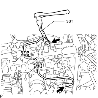
Text in Illustration *1 Rubber Grommet *2 Rubber Mount Install the fuel inlet pipe sub-assembly to the rubber grommet and rubber mount as shown in the illustration.
Note
Install the rubber mount and rubber grommet at the correct positions on the pressure line.
-
Temporarily install the union nut at the fuel supply pump assembly end and common rail assembly end of the fuel inlet pipe sub-assembly by hand.
-
Using SST, tighten the union nut at the fuel supply pump assembly end and common rail assembly end of the fuel inlet pipe sub-assembly as shown in the illustration.
SST PZ4TB-04959-10 - Torque:
- 24 N*m { 245 kgf*cm, 18 ft.*lbf }
Note
Reset SST in a timely manner to prevent bending of pressure lines.
-
-
INSTALL INJECTION PIPE SUB-ASSEMBLY
-
INSTALL INTAKE MANIFOLD
-
INSPECT FOR FUEL LEAK