COMMON RAIL REMOVAL
CAUTION / NOTICE / HINT
Note
-
After the engine has stopped, wait at least 1 minute before releasing the high pressure lines.
-
When working on the fuel circuit, protect the generator assembly against dirt contamination.
Cover the generator assembly with suitable materials.
Failure to comply with this procedure may result in a generator assembly malfunction.
-
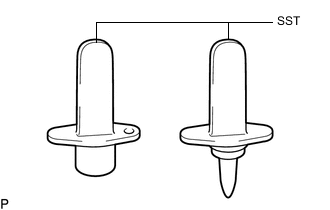
After disconnecting the pressure line, it is absolutely essential to seal the injector assemblies and the common rail assembly with SST.
SST PZ4TB-04941-79
PROCEDURE
-
REMOVE INTAKE MANIFOLD
-
REMOVE INJECTION PIPE SUB-ASSEMBLY
-
REMOVE FUEL INLET PIPE SUB-ASSEMBLY
-
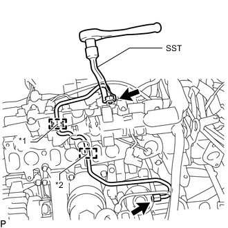
Text in Illustration *1 Rubber Grommet *2 Rubber Mount Using SST, loosen the union nut at the common rail assembly end of the fuel inlet pipe sub-assembly.
SST PZ4TB-04959-10 Note
Reset SST in a timely manner to prevent bending of pressure lines.
-
Using SST, loosen the union nut at the fuel supply pump assembly end of the fuel inlet pipe sub-assembly.
SST PZ4TB-04959-10 Note
Reset SST in a timely manner to prevent bending of pressure lines.
-
Remove the fuel inlet pipe sub-assembly from the rubber grommet and rubber mount.
-
-
REMOVE COMMON RAIL ASSEMBLY
-
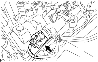
Disconnect the fuel pressure sensor connector.
-
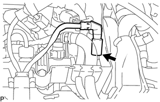
Disconnect the pressure discharge valve connector.
-
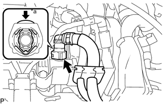
Text in Illustration *a Push Push at the location shown in the illustration and disconnect the fuel return tube.
-
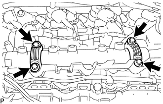
Using an E10 "TORX" socket wrench, remove the 4 bolts and 2 common rail assembly brackets.
-
Remove the common rail assembly from the cylinder head cover sub-assembly.
-
-
REMOVE FUEL PRESSURE SENSOR
-
REMOVE PRESSURE DISCHARGE VALVE