FUEL SUPPLY PUMP INSTALLATION
CAUTION / NOTICE / HINT
Note
-
SST A remains in the timing chain cover plate.
-
Always be sure to check the tightening torque.
-
If the pressure lines are leaking after installation, they must be replaced.
-
Do not overtighten the pressure lines.
PROCEDURE
-
INSTALL FUEL SUPPLY PUMP ASSEMBLY
-
Install the fuel quantity control valve with the 2 bolts.
Tech Tips
Refer to "SPECIFICATIONS - STANDARD BOLT" for the tightening torque.
-
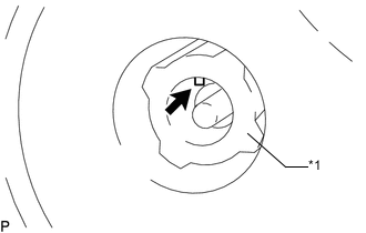
Text in Illustration *1 Injection Pump Drive Gear To insert the fuel supply pump assembly shaft in the injection pump drive gear, it may be necessary to turn the fuel supply pump assembly several degrees so that the spline indicated by the arrow in the illustration and the groove in the fuel supply pump assembly shaft are aligned. Then rotate the fuel supply pump assembly back to the position where the screw can be installed.
-
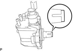
Install the fuel supply pump assembly to the cylinder block.
Note
Do not damage the shaft, especially the taper.
Tech Tips
When installing a new fuel supply pump assembly, adjust the fuel supply pump assembly injection pump drive gear assignment by turning the fuel supply pump assembly back 45° clockwise (top view).
-
Tighten the central bolt connection between the fuel supply pump assembly and injection pump drive gear.
- Torque:
- 65 N*m { 663 kgf*cm, 48 ft.*lbf }
-
Install the 2 bolts to the fuel supply pump assembly.
- Torque:
- 19 N*m { 194 kgf*cm, 14 ft.*lbf }
-
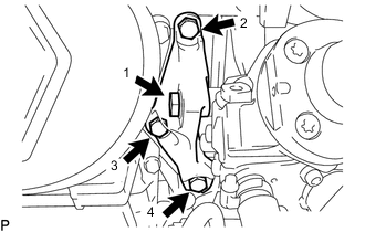
Temporarily install the fuel supply pump assembly support with the 4 bolts by hand in the order shown in the illustration.
-
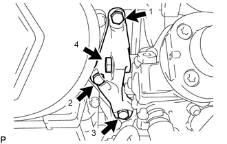
Tighten the 4 bolts in the order shown in the illustration.
- Torque:
- 19 N*m { 194 kgf*cm, 14 ft.*lbf }
-
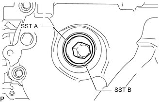
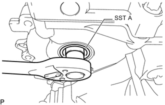
Install SST B to SST A, and then remove both SST A and SST B.
SST PZ4TB-04967-25 -
Apply a light coat of engine oil to a new O-ring, and install it to the sealing cap.
-
Install the sealing cap to the timing chain cover plate.
- Torque:
- 20 N*m { 204 kgf*cm, 15 ft.*lbf }
-
Install 2 new clamps to the fuel feed line hose and fuel return line hose.
-
Connect the fuel feed line hose and fuel return line hose to the fuel supply pump assembly and tighten the 2 clamps.
- Torque:
- 3.0 N*m { 31 kgf*cm, 27 in.*lbf }
-
Connect the connector to the fuel quantity control valve.
-
Release the No. 1 cylinder set to TDC/compression.
-
-
INSTALL FUEL INLET PIPE SUB-ASSEMBLY
-
INSPECT FOR FUEL LEAK
-
PERFORM INITIALIZATION