FUEL INJECTOR INSTALLATION
CAUTION / NOTICE / HINT
Note
-
Always be sure to check the tightening torque.
-
If the pressure lines are leaking after installation, they must be replaced.
-
Do not overtighten the pressure lines.
PROCEDURE
-
INSTALL INJECTOR ASSEMBLY
Note
-
Before installing the injector assembly, check for carbon, foreign matter, etc. on the seal surfaces of the cylinder head sub-assembly and injector assembly. If there is foreign matter, remove it before installing the injector assembly.
-
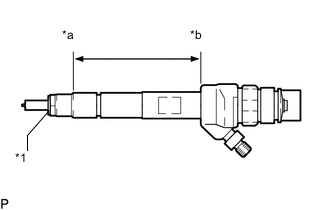
Make sure to replace the copper sealing ring on the injector assembly.
Text in Illustration *1 Copper Sealing Ring *a Point Above the Copper Sealing Ring *b Injector Assembly Slot End -
Before installing the injector assemblies to the injector assembly slots, apply a light coat of highly heat-resistant grease from above the top of the copper sealing ring to the injector assembly slot end.
-
Check the installation position of the high pressure connection.
-
Make sure to read the adjustment values each time new injector assemblies are installed.
-
Install the 4 injector assemblies to the cylinder head cover sub-assembly.
-
Using an E10 "TORX" socket wrench, install the 4 clamping claws to the 4 injector assemblies with the 4 centering rings and 4 bolts.
- Torque:
- 10 N*m { 102 kgf*cm, 7 ft.*lbf }
Note
-
Retighten the clamping claw (cylinder head cover mounting).
-
Make sure the screw centering ring is correctly positioned in order to align the clamping claw.
-
Connect the 4 injector assembly connectors.
-
-
CONNECT NOZZLE LEAKAGE PIPE ASSEMBLY
-
Install 4 new sealing rings to the nozzle leakage pipe assembly.
-

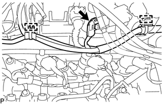
Text in Illustration *1 Sealing Ring *2 Leakage Line *3 Clip *a Push Down Connect the nozzle leakage pipe assembly to the 4 injector assemblies and push down the 4 clips to install the nozzle leakage pipe assembly.
-
Connect the connector and attach the 2 clamps to connect the wire harness.
-
-
INSTALL CAMSHAFT POSITION SENSOR ASSEMBLY
-
INSTALL INJECTION PIPE SUB-ASSEMBLY
Note
-
If the pressure lines are leaking after installation, they must be replaced.
-
Do not overtighten the pressure lines.
-
Temporarily install the 2 No. 1 injection pipe sub-assemblies and 2 No. 2 injection pipe sub-assemblies at the common rail assembly end by hand.
-
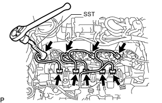
Using a SST, tighten the 4 union nuts at the common rail assembly end of the 2 No. 1 injection pipe sub-assemblies and 2 No. 2 injection pipe sub-assemblies as shown in the illustration.
SST PZ4TB-04959-10 - Torque:
- 24 N*m { 245 kgf*cm, 18 ft.*lbf }
Note
Reset SST in a timely manner to prevent bending of pressure lines.
-
Using SST, tighten the 4 union nuts at the 4 injector assembly ends of the 2 No. 1 injection pipe sub-assemblies and 2 No. 2 injection pipe sub-assemblies.
SST PZ4TB-04959-10 - Torque:
- 24 N*m { 245 kgf*cm, 18 ft.*lbf }
Note
Reset SST in a timely manner to prevent bending of pressure lines.
-
Check all components of the common rail system for tightness.
-
-
CONNECT CABLE TO NEGATIVE BATTERY TERMINAL
Note
When disconnecting the cable, some systems need to be initialized after the cable is reconnected Click here.
-
PERFORM REGISTRATION
-
INSTALL ENGINE COVER
-
INSTALL NO. 1 ENGINE COVER
-
INSPECT FOR FUEL LEAK