FUEL SUPPLY PUMP INSTALLATION
CAUTION / NOTICE / HINT
Note
-
When replacing the injectors (including shuffling the injectors between the cylinders), common rail, intake manifold or cylinder head, it is necessary to replace the injection pipes with new ones.
-
When replacing the fuel supply pump, common rail, intake manifold or cylinder head, it is necessary to replace the fuel inlet pipe with a new one.
PROCEDURE
-
INSTALL FUEL SUPPLY PUMP ASSEMBLY
-
Apply a light coat of engine oil to a new O-ring.
-
Install the O-ring to the supply pump.
-
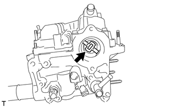
Install the supply pump drive coupling.
Note
When reusing the coupling, it must be installed in the same orientation (top/bottom, front/back) as when it was removed.
Tech Tips
Line up the coupling with the groove in the camshaft end.
-
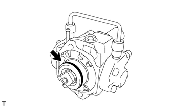
Install the supply pump with the 2 bolts.
- Torque:
- 21 N*m { 209 kgf*cm, 15 ft.*lbf }
Tech Tips
Line up the end of the supply pump drive shaft with the supply pump drive coupling.
-
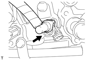
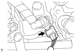
Connect the suction control valve connector.
-
Connect the fuel temperature sensor connector.
-
-
INSTALL FUEL TUBE SUB-ASSEMBLY
-
Temporarily install the fuel tube and 2 new gaskets with the check valve and union bolt.
-
Tighten the check valve.
- Torque:
- 32 N*m { 321 kgf*cm, 23 ft.*lbf }
-
Tighten the union bolt.
- Torque:
- 23 N*m { 235 kgf*cm, 17 ft.*lbf }
-
Connect the fuel tube connector to the injector.
-
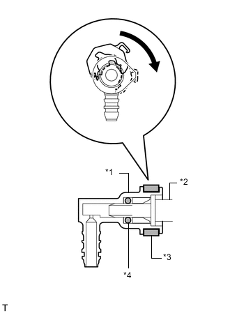
Text in Illustration *1 Fuel Tube Connector *2 Injector *3 Retainer *4 O-Ring Turn the retainer in the direction indicated by the arrow until it makes a "click" sound.
Note
If the fuel tube connector is not inserted to the correct position on the injector, the retainer cannot be turned far enough in the direction of the arrow.
-
Connect the exhaust fuel addition injector connector.
-
-
INSTALL FUEL HOSE PROTECTOR
-
INSTALL FUEL INLET PIPE SUB-ASSEMBLY
-
Temporarily install the fuel inlet pipe with the 2 clamps and nut.
-
Using a 14 mm union nut wrench, first tighten the nut at the common rail end of the fuel inlet pipe.
- Torque:
- 30 N*m { 306 kgf*cm, 22 ft.*lbf }
Note
Use the formula to calculate special torque values for situations where a union nut wrench is combined with a torque wrench Click here.
-
Using a 14 mm union nut wrench, tighten the nut at the supply pump end of the fuel inlet pipe.
- Torque:
- 30 N*m { 306 kgf*cm, 22 ft.*lbf }
Note
Use the formula to calculate special torque values for situations where a union nut wrench is combined with a torque wrench Click here.
-
Tighten the No. 2 injection pipe clamp nut.
- Torque:
- 5.0 N*m { 51 kgf*cm, 44 in.*lbf }
-
-
INSTALL NO. 1 FUEL HOSE
-
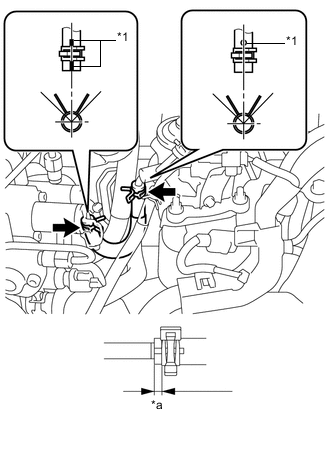
Text in Illustration *1 Alignment Mark *a 1 to 5 mm (0.0394 to 0.197 in.) Using pliers, grip the claws of the 2 clips and slide the 2 clips to install the No. 1 fuel hose.
Tech Tips
-
Align the alignment marks and connect the hose.
-
Align the claws of the clamp with the hose alignment mark as shown in the illustration.
-
Position the clamp so that the distance from the end of the hose is 1 to 5 mm (0.0394 to 0.197 in.).
-
-
-
INSTALL NO. 3 FUEL HOSE
-
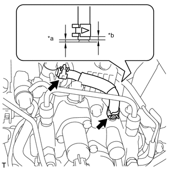
Text in Illustration *a 2 to 3 mm (0.0787 to 0.118 in.) *b 2 to 6 mm (0.0787 to 0.236 in.) Using pliers, grip the claws of the 2 clips and slide the 2 clips to install the No. 3 fuel hose.
Tech Tips
-
Push on the fuel hose so that the clearance is 2 to 3 mm (0.0787 to 0.118 in.).
-
Position the clamp so that the distance from the end of the hose is 2 to 6 mm (0.0787 to 0.236 in.).
-
-
-
INSTALL AIR CLEANER CASE SUB-ASSEMBLY
-
INSTALL AIR CLEANER FILTER ELEMENT SUB-ASSEMBLY
-
INSTALL AIR CLEANER CAP SUB-ASSEMBLY
-
CONNECT CABLE TO NEGATIVE BATTERY TERMINAL
Note
When disconnecting the cable, some systems need to be initialized after the cable is reconnected Click here.
-
PERFORM INITIALIZATION
-
w/ Gear Shift Indicator:
-
w/o Gear Shift Indicator:
-
-
BLEED AIR FROM FUEL SYSTEM
-
INSPECT FOR FUEL LEAK
-
INSTALL NO. 1 ENGINE COVER