ENGINE UNIT DISASSEMBLY

CAUTION / NOTICE / HINT
Note
-
After the engine has stopped, wait at least 1 minute before releasing the high pressure lines.
-
When working on the fuel circuit, protect the generator assembly against dirt contamination. Cover generator assembly with suitable materials. Failure to comply with this procedure may result in a generator assembly malfunction.
-
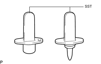
After disconnecting the pressure line, it is absolutely essential to seal the injector assemblies and the common rail assembly with SST.
SST PZ4TB-04941-79
PROCEDURE
-
REMOVE CAMSHAFT POSITION SENSOR
-
REMOVE CRANKSHAFT POSITION SENSOR
-
REMOVE ENGINE COOLANT TEMPERATURE SENSOR
-
REMOVE ENGINE OIL PRESSURE SWITCH ASSEMBLY
-
REMOVE NOZZLE LEAKAGE PIPE ASSEMBLY
-
REMOVE INJECTOR ASSEMBLY
-
REMOVE ENGINE WATER PUMP ASSEMBLY
-
REMOVE WATER BY-PASS PIPE
-
Using a 5 mm hexagon socket wrench, remove the bolt and water by-pass pipe from the water inlet housing.
-
-
REMOVE WATER INLET
-
REMOVE THERMOSTAT
-
REMOVE WATER INLET HOUSING
-
Using an E11 "TORX" socket wrench, remove the 5 bolts and water inlet housing.
-
-
REMOVE WATER OUTLET
-
Using an E10 "TORX" socket wrench, remove the 3 bolts and water outlet.
-
Remove the gasket from the water outlet.
-
-
REMOVE OIL FILTER SUB-ASSEMBLY
-
REMOVE OIL FILTER ASSEMBLY
-
SET NO. 1 CYLINDER TO TDC/COMPRESSION
-
REMOVE OIL FILLER CAP SUB-ASSEMBLY
-
REMOVE CYLINDER HEAD COVER SUB-ASSEMBLY
-
HOLDING CAMSHAFT AND NO. 2 CAMSHAFT
-
REMOVE NO. 2 CHAIN TENSIONER ASSEMBLY
-
REMOVE NO. 2 TIMING CHAIN GUIDE
-
REMOVE CAMSHAFT AND NO. 2 CAMSHAFT
-
REMOVE CAMSHAFT HOUSING SUB-ASSEMBLY
-
REMOVE NO. 1 VALVE ROCKER ARM SUB-ASSEMBLY
-
REMOVE VALVE LASH ADJUSTER ASSEMBLY
-
REMOVE CYLINDER HEAD SUB-ASSEMBLY
-
REMOVE CYLINDER HEAD GASKET
-
Remove the cylinder head gasket from the cylinder block.
-
-
REMOVE CRANKSHAFT PULLEY
-
REMOVE TIMING GEAR CASE OR TIMING CHAIN CASE OIL SEAL
-
REMOVE CLUTCH COVER ASSEMBLY
-
REMOVE CLUTCH DISC ASSEMBLY
-
REMOVE FLYWHEEL WITH DAMPER ASSEMBLY
-
REMOVE FUEL SUPPLY PUMP ASSEMBLY
-
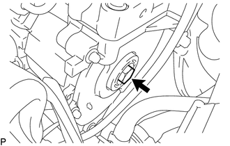
Remove the sealing cap from the timing chain cover plate.
-
Remove the O-ring from the sealing cap.
-
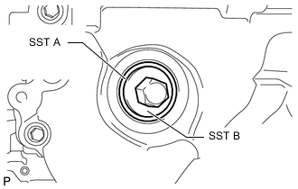
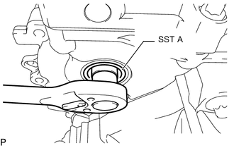
Using SST B, install SST A to position the fuel supply pump assembly. Then remove SST B.
SST PZ4TB-04967-25 Note
SST A remains in the timing chain cover plate until the end of the repair work.
-
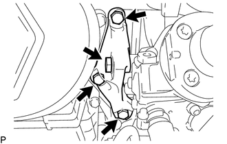
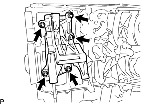
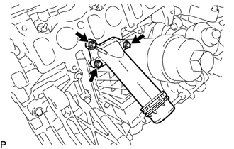
Remove the 4 bolts and fuel supply pump assembly support.
-
Remove the 2 bolts from the fuel supply pump assembly.
-
Text in Illustration *1 Central Bolt Remove the screw connection between the fuel supply pump assembly and injection pump drive gear.
Note
-
SST A remains in the timing chain cover plate.
-
The central bolt is supported on SST A until the fuel supply pump assembly pressed out.
-
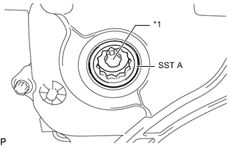
The central bolt remains inside SST A attached to the injection pump drive gear.
-
-
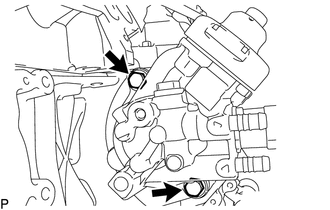
Remove the fuel supply pump assembly from the cylinder block.
-
-
REMOVE OIL PAN SUB-ASSEMBLY
-
REMOVE OIL STRAINER SUB-ASSEMBLY
-
REMOVE OIL PUMP WITH VACUUM PUMP ASSEMBLY
-
REMOVE REAR ENGINE OIL SEAL
-
REMOVE TIMING CHAIN COVER PLATE
-
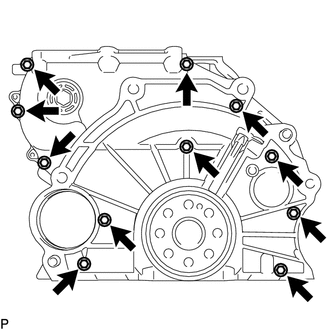
Using an E8 "TORX" socket wrench, remove the 11 bolts and timing chain cover plate.
-
-
REMOVE OIL PUMP DRIVE CHAIN SUB-ASSEMBLY
-
Remove the oil pump drive chain sub-assembly from the crankshaft.
-
-
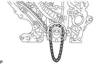
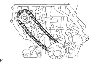
REMOVE NO. 2 CHAIN SUB-ASSEMBLY
-
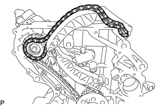
Remove the No. 2 chain sub-assembly from the injection pump drive gear.
-
-
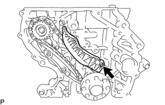
REMOVE NO. 2 TIMING CHAIN TENSION ARM
-
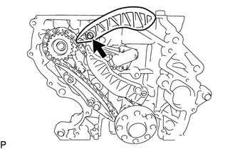
Using a T45 "TORX" socket wrench, remove the bolt and No. 2 timing chain tension arm.
-
-
REMOVE NO. 1 CHAIN TENSIONER ASSEMBLY
-
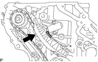
Text in Illustration *a Hexagon Wrench Slowly push the plunger deep into the No. 1 chain tensioner assembly and insert a 3.0 mm hexagon wrench into the No. 1 chain tensioner assembly.
-
Using an E8 "TORX" socket wrench, remove the 2 bolts and No. 1 chain tensioner assembly.
-
-
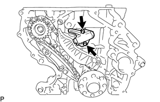
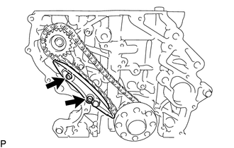
REMOVE TIMING CHAIN TENSION ARM
-
Using a T45 "TORX" socket wrench, remove the bolt and timing chain tension arm.
-
-
REMOVE TIMING CHAIN GUIDE
-
Using a T45 "TORX" socket wrench, remove the 2 bolts and timing chain guide.
-
-
REMOVE INJECTION PUMP DRIVE GEAR
-
Remove the injection pump drive gear and chain sub-assembly.
-
-
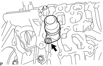
REMOVE NO. 2 OIL NOZZLE SUB-ASSEMBLY
-
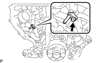
Using an E8 "TORX" socket wrench, remove the bolt and No. 2 oil nozzle sub-assembly.
-