CYLINDER HEAD REPLACEMENT

PROCEDURE
-
REPLACE INTAKE VALVE GUIDE BUSH
-
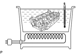
Gradually heat the cylinder head to 80 to 100°C (176 to 212°F).
-
Place the cylinder head on a wooden block.
-
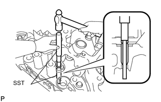
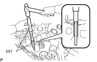
Using SST and a hammer, tap out the valve guide bush.
- SST
- 09201-10000
- 09950-70010
-
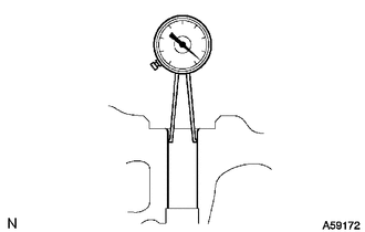
Using a caliper gauge, measure the bush bore diameter of the cylinder head.
If the bush bore diameter of the cylinder head is more than 11.006 mm (0.433 in.), machine the bush bore diameter to between 11.035 and 11.056 mm (0.434 and 0.435 in.).
If the bush bore diameter of the cylinder head is more than 11.056 mm (0.435 in.), replace the cylinder head.
-
Select a new guide bush (STD or O/S 0.05).
Guide Bush Bush Size Specified Condition Use STD 10.985 to 11.006 mm (0.432 to 0.433 in.) Use O/S 0.05 11.035 to 11.056 mm (0.434 to 0.435 in.) -
Gradually heat the cylinder head to 80 to 100°C (176 to 212°F).
-
Place the cylinder head on a wooden block.
-
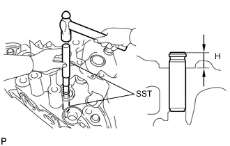
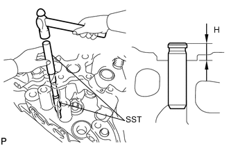
Using SST and a hammer, tap in a new guide bush to the specified protrusion height.
- SST
- 09201-10000
- 09950-70010
Standard protrusion height (H) 9.0 to 9.4 mm (0.354 to 0.370 in.) -
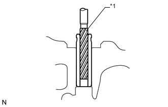
Text in Illustration *1 Sharp 6.0 mm Reamer Using a sharp 6.0 mm reamer, ream the valve guide bush to obtain the standard specified clearance between the valve guide bush and valve stem.
-
-
REPLACE EXHAUST VALVE GUIDE BUSH
-
Gradually heat the cylinder head to 80 to 100°C (176 to 212°F).
-
Place the cylinder head on a wooden block.
-
Using SST and a hammer, tap out the valve guide bush.
- SST
- 09201-10000
- 09950-70010
-
Using a caliper gauge, measure the bush bore diameter of the cylinder head.
If the bush bore diameter of the cylinder head is more than 11.006 mm (0.433 in.), machine the bush bore diameter to between 11.035 and 11.056 mm (0.434 and 0.435 in.).
If the bush bore diameter of the cylinder head is more than 11.056 mm (0.435 in.), replace the cylinder head.
-
Select a new guide bush (STD or O/S 0.05).
Guide Bush Bush Size Specified Condition Use STD 10.985 to 11.006 mm (0.432 to 0.433 in.) Use O/S 0.05 11.035 to 11.056 mm (0.434 to 0.435 in.) -
Gradually heat the cylinder head to 80 to 100°C (176 to 212°F).
-
Place the cylinder head on a wooden block.
-
Using SST and a hammer, tap in a new guide bush to the specified protrusion height.
- SST
- 09201-10000
- 09950-70010
Standard protrusion height (H) 9.0 to 9.4 mm (0.354 to 0.370 in.) -
Text in Illustration *1 Sharp 6.0 mm Reamer Using a sharp 6.0 mm reamer, ream the valve guide bush to obtain the standard specified clearance between the valve guide bush and valve stem.
-
-
REPLACE CYLINDER HEAD RING PIN
Tech Tips
It is not necessary to remove the ring pin unless it is being replaced.
-
Remove the ring pin.
-
Using a plastic-faced hammer, tap in a new ring pin until the pin stops.
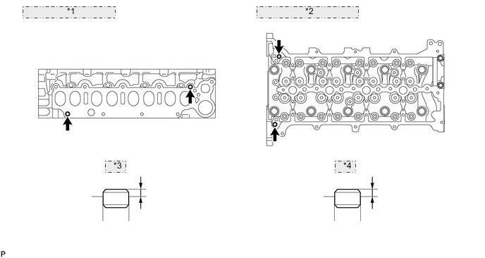
*1 Intake Manifold Side: *2 Cylinder Head Cover Side: *3 Pin A *4 Pin B Standard Protrusion Item Specified Condition Pin A 3.9 to 5.5 mm (0.154 to 0.217 in.) Pin B 2.5 to 3.5 mm (0.0984 to 0.138 in.)
-
-
REPLACE NO. 1 STRAIGHT SCREW PLUG WITH HEAD
-
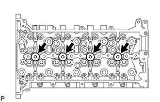
Using a 6 mm hexagon wrench, remove the straight screw plugs.
-
Apply adhesive to new straight screw plugs.
Adhesive Toyota Genuine Adhesive 1324, Three Bond 1324 or equivalent -
Using a 6 mm hexagon wrench, install the straight screw plugs.
- Torque:
- 25 N*m { 255 kgf*cm, 18 ft.*lbf }
-
-
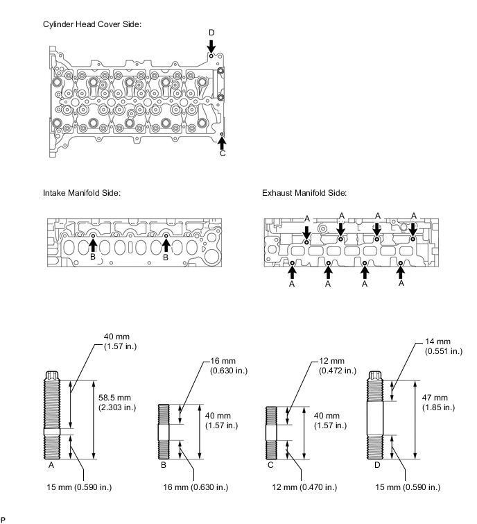
REPLACE CYLINDER HEAD STUD BOLT
Tech Tips
If a stud bolt is deformed or the threads are damaged, replace it.
-
Remove the stud bolts.
-
Using an E8 "TORX" socket wrench, install new stud bolts.
- Torque:
- for stud bolt A and B
- 12 N*m { 122 kgf*cm, 9 ft.*lbf }
- for stud bolt C
- 5.0 N*m { 51 kgf*cm, 44 in.*lbf }
- for stud bolt D
- 8.0 N*m { 82 kgf*cm, 71 in.*lbf }
-