ENGINE UNIT INSTALLATION

CAUTION / NOTICE / HINT
Note
-
When replacing the injectors (including shuffling the injectors between the cylinders), common rail, intake manifold or cylinder head, it is necessary to replace the injection pipes with new ones.
-
When replacing the fuel supply pump, common rail, intake manifold or cylinder head, it is necessary to replace the fuel inlet pipe with a new one.
PROCEDURE
-
INSTALL DRIVE SHAFT BEARING BRACKET
-
Install the bearing bracket with the 3 bolts.
- Torque:
- 64 N*m { 653 kgf*cm, 47 ft.*lbf }
-
-
INSTALL EXHAUST MANIFOLD WITH TURBOCHARGER SUB-ASSEMBLY
-
INSTALL NO. 2 TURBO OIL PIPE
-
INSTALL NO. 5 WATER BY-PASS PIPE (for Automatic Transaxle)
-
INSTALL NO. 2 TURBO WATER PIPE SUB-ASSEMBLY (for Manual Transaxle)
-
CONNECT NO. 3 WATER BY-PASS HOSE
-
INSTALL NO. 1 TURBO WATER PIPE SUB-ASSEMBLY (for Manual Transaxle)
-
INSTALL NO. 1 TURBO INSULATOR
-
INSTALL TURBO OIL OUTLET PIPE
-
INSTALL EGR COOLER WITH PIPE ASSEMBLY
-
INSTALL NO. 2 WATER BY-PASS HOSE (for Automatic Transaxle)
-
INSTALL NO. 5 WATER BY-PASS HOSE (for Manual Transaxle)
-
INSTALL NO. 1 TURBO WATER HOSE (for Manual Transaxle)
-
INSTALL EXHAUST MANIFOLD CONVERTER SUB-ASSEMBLY
-
INSTALL NO. 1 MANIFOLD CONVERTER INSULATOR
-
INSTALL VACUUM TRANSMITTING HOSE ASSEMBLY
-
INSTALL NO. 1 VACUUM SWITCHING VALVE ASSEMBLY
-
INSTALL VACUUM REGULATING VALVE ASSEMBLY
-
INSTALL NO. 1 TURBO OIL PIPE
-
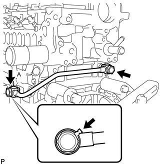
Install the oil pipe and 2 new gaskets with the 2 union bolts.
- Torque:
- 35 N*m { 357 kgf*cm, 26 ft.*lbf }
Tech Tips
Be sure to install union bolt A so that the gasket is positioned as shown in the illustration.
-
-
INSTALL NO. 3 WATER BY-PASS PIPE
-
Apply soapy water to a new O-ring and install it to the by-pass pipe.
-
Install the No. 3 water by-pass pipe with the 2 bolts.
- Torque:
- 21 N*m { 214 kgf*cm, 15 ft.*lbf }
-
-
INSTALL FUEL HOSE PROTECTOR
-
Install the fuel hose protector to the cylinder head.
- Torque:
- 21 N*m { 214 kgf*cm, 15 ft.*lbf }
-
-
INSTALL SUPPLY PUMP ASSEMBLY
-
Install a new O-ring to the supply pump.
-
Install the supply pump drive coupling.
Tech Tips
Line up the coupling with the groove in the camshaft end.
Note
When reusing the coupling, it must be installed in the same orientation (top/bottom, front/back) as when it was removed,
-
Install the supply pump with the 2 bolts.
- Torque:
- 21 N*m { 209 kgf*cm, 15 ft.*lbf }
Tech Tips
Line up the end of the supply pump drive shaft with the supply pump drive coupling.
Note
Apply engine oil to the O-ring of the supply pump.
-
-
INSTALL NO. 3 FUEL HOSE
-
INSTALL FUEL INJECTOR SEAL
-
INSTALL EXHAUST FUEL ADDITION INJECTOR ASSEMBLY
-
INSTALL FUEL TUBE SUB-ASSEMBLY
-
INSTALL FUEL HOSE PROTECTOR
-
INSTALL NO. 2 WATER BY-PASS PIPE
-
INSTALL NO. 4 WATER BY-PASS HOSE
-
INSTALL NO. 8 WATER BY-PASS HOSE
-
INSTALL NO. 6 WATER BY-PASS HOSE
-
INSTALL WATER BY-PASS HOSE
-
INSTALL NO. 1 CYLINDER BLOCK INSULATOR
-
INSTALL GLOW PLUG ASSEMBLY
-
Using a 10 mm deep socket wrench, install the 4 glow plugs.
- Torque:
- 12 N*m { 125 kgf*cm, 9 ft.*lbf }
-
Install the glow plug connector with the 4 nuts.
- Torque:
- 2.2 N*m { 22 kgf*cm, 19 in.*lbf }
-
Install the 4 grommets.
-
-
INSTALL INTAKE MANIFOLD
-
INSTALL NO. 2 INTAKE MANIFOLD
-
INSTALL ENGINE COVER BRACKET
-
INSTALL GAS FILTER BRACKET
-
INSTALL NO. 1 GAS FILTER
-
INSTALL DIESEL TURBO PRESSURE SENSOR
-
INSTALL INTAKE MANIFOLD INSULATOR
-
INSTALL COMMON RAIL ASSEMBLY
-
INSTALL NO. 4 FUEL HOSE
-
INSTALL INJECTION PIPE SUB-ASSEMBLY
-
INSTALL FUEL INLET PIPE SUB-ASSEMBLY
-
INSTALL ENGINE OIL LEVEL DIPSTICK GUIDE
-
INSTALL ELECTRIC EGR CONTROL VALVE ASSEMBLY
-
INSTALL NO. 2 EGR PIPE SUB-ASSEMBLY
-
INSTALL EGR VALVE BRACKET
-
CONNECT NO. 8 WATER BY-PASS HOSE
-
INSTALL NO. 7 WATER BY-PASS HOSE
-
INSTALL DIESEL THROTTLE BODY ASSEMBLY
-
INSTALL VACUUM PUMP ASSEMBLY
-
INSTALL V-RIBBED BELT TENSIONER ASSEMBLY
-
Install the belt tensioner with the 3 bolts.
- Torque:
- 20 N*m { 204 kgf*cm, 15 ft.*lbf }
Note
As the bolts' heads are not as thick as typical bolts, be careful not to damage them during installation.
-
-
INSTALL ENGINE MOUNTING BRACKET
-
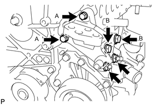
Set the mounting bracket on the engine.
-
Temporarily install the 2 bolts labeled B and 2 nuts.
-
Install the 2 bolts labeled A.
- Torque:
- for bolt A
- 28 N*m { 286 kgf*cm, 21 ft.*lbf }
-
Tighten the 2 bolts labeled B and 2 nuts.
- Torque:
- for bolt B, nut
- 80 N*m { 816 kgf*cm, 59 ft.*lbf }
-
-
INSTALL NO. 4 WATER BY-PASS PIPE
-
Install a new O-ring to the No. 4 water by-pass pipe.
-
Install the No. 4 water by-pass pipe with the bolt.
- Torque:
- 11 N*m { 112 kgf*cm, 8 ft.*lbf }
-
-
INSTALL NO. 1 IDLER PULLEY SUB-ASSEMBLY
-
Install the idler pulley with the bolt.
- Torque:
- 40 N*m { 408 kgf*cm, 30 ft.*lbf }
-
-
INSTALL IDLER PULLEY COVER PLATE
-
Install the idler pulley cover plate.
-
-
INSTALL NO. 2 IDLER PULLEY SUB-ASSEMBLY
-
Install the idler pulley and plate with the bolt.
- Torque:
- 40 N*m { 408 kgf*cm, 30 ft.*lbf }
-
-
INSTALL GENERATOR ASSEMBLY
-
Install the generator with the 3 bolts.
- Torque:
- 25 N*m { 255 kgf*cm, 18 ft.*lbf }
-
-
INSTALL COMPRESSOR STAY
-
Install the compressor stay to the cylinder block.
- Torque:
- 35 N*m { 357 kgf*cm, 26 ft.*lbf }
-