ENGINE UNIT REASSEMBLY

CAUTION / NOTICE / HINT
Note
-
When replacing the injectors (including shuffling the injectors between the cylinders), common rail, intake manifold or cylinder head, it is necessary to replace the injection pipes with new ones.
-
When replacing the fuel supply pump, common rail, intake manifold or cylinder head, it is necessary to replace the fuel inlet pipe with a new one.
PROCEDURE
-
INSTALL CYLINDER BLOCK DRAIN COCK PLUG
-
Apply adhesive to the cylinder block drain cock plug.
Seal packing Toyota Genuine Seal Packing 1282B, Three Bond 1282B or equivalent -
Install the cylinder block drain cock plug.
- Torque:
- 25 N*m { 255 kgf*cm, 18 ft.*lbf }
-
-
INSTALL ENGINE BALANCER ASSEMBLY
-
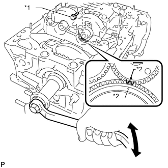
Text in Illustration *1 Service Bolt *2 Align Turn the crankshaft with a wrench to align the timing mark of the drive gear with that of the driven gear (1 dot mark each), and then mesh the gears and install the engine balancer to the engine.
-
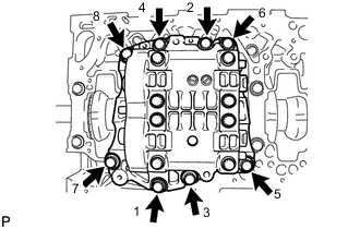
Temporarily install the engine balancer bolts.
Tech Tips
The engine balancer bolts are tightened in 2 progressive steps.
-
Step 1
-
Uniformly tighten the 8 bolts in several passes in the sequence shown in the illustration.
- Torque:
- 50 N*m { 510 kgf*cm, 37 ft.*lbf }
-
-
Step 2
-
Mark the front of the engine balancer bolts with paint.
-
Tighten the engine balancer bolts by 90°.
-
Check that the painted marks are now at a 90° angle to the front.
-
-
Remove the service bolt from the engine balancer.
-
-
INSTALL OIL BAFFLE PLATE
-
Install the oil baffle plate with the 2 bolts.
- Torque:
- 9.0 N*m { 92 kgf*cm, 80 in.*lbf }
-
-
INSTALL REAR CRANKSHAFT OIL SEAL
-
Coat the lip of a new oil seal with MP grease.
-
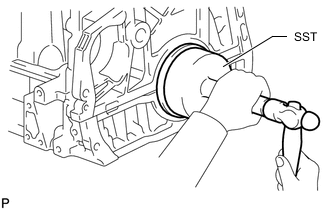
Using SST, tap in the oil seal until its surface is flush with the oil seal retainer edge.
- SST
- 09223-56010
Note
-
Keep the lip free from foreign matter.
-
Do not tap the oil seal at an angle.
-
-
SELECT CYLINDER HEAD GASKET
-
INSTALL CYLINDER HEAD GASKET
-
INSTALL CYLINDER HEAD SUB-ASSEMBLY
-
INSPECT VALVE LASH ADJUSTER ASSEMBLY
-
INSTALL VALVE LASH ADJUSTER ASSEMBLY
-
INSTALL NO. 1 VALVE ROCKER ARM SUB-ASSEMBLY
-
INSTALL CAMSHAFT
-
INSTALL CRANKSHAFT PULLEY SET CRANKSHAFT KEY
-
Install the 2 keys to the crankshaft.
-
-
INSTALL CAMSHAFT TIMING SPROCKET
-
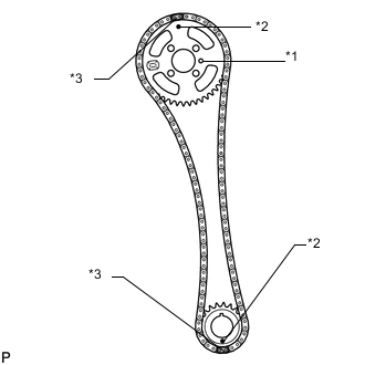
Text in Illustration *1 Straight Pin *2 Timing Mark *3 Yellow Paint Mark Install the crankshaft timing sprocket and camshaft timing sprocket to the chain so that the timing marks of the sprockets and paint marks of the chain are aligned.
-
Install the camshaft timing sprocket to the No. 2 camshaft by fitting the straight pin of the No. 2 camshaft into the hole on the camshaft timing sprocket.
-
Install the crankshaft timing sprocket to the crankshaft.
-
While holding the hexagon portion of the No. 2 camshaft, install and uniformly tighten the 4 bolts of the No. 2 camshaft.
- Torque:
- 20 N*m { 204 kgf*cm, 15 ft.*lbf }
-
-
INSTALL OIL PUMP DRIVE GEAR
-
Install the oil pump drive gear to the crankshaft.
-
-
INSTALL NO. 1 CHAIN VIBRATION DAMPER
-
Install the No. 1 chain vibration damper with the 2 bolts.
- Torque:
- 21 N*m { 214 kgf*cm, 15 ft.*lbf }
-
-
INSTALL CHAIN TENSIONER SLIPPER
-
Install the chain tensioner slipper.
-
-
INSTALL NO. 1 CHAIN TENSIONER ASSEMBLY
-
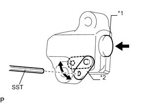
Text in Illustration *1 Plunger *2 Stopper Plate Move the stopper plate upward to release the lock, and push the plunger deep into the tensioner.
-
Move the stopper plate downward to set the lock, and insert SST into the stopper plate hole.
- SST
- 09240-00020 ( 09242-00200 )
-
Install the chain tensioner with the 2 bolts.
- Torque:
- 9.0 N*m { 92 kgf*cm, 80 in.*lbf }
-
Remove SST.
-
-
INSTALL FRONT CRANKSHAFT OIL SEAL
-
INSTALL TIMING CHAIN COVER SUB-ASSEMBLY
-
INSTALL CRANKSHAFT PULLEY
-
Align the keyway of the pulley with the key located on the crankshaft, and then slide the pulley into place to install it.
-
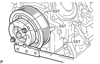
Using SST, install a new pulley bolt.
- SST
- 09213-58014 ( 91551-80840 )
- 09330-00021
- Torque:
- 300 N*m { 3059 kgf*cm, 221 ft.*lbf }
-
-
INSTALL OIL STRAINER SUB-ASSEMBLY
-
INSTALL OIL FILTER BRACKET
-
INSTALL OIL FILTER ELEMENT
-
INSTALL NO. 2 OIL PAN SUB-ASSEMBLY
-
INSTALL CYLINDER HEAD COVER SUB-ASSEMBLY
-
INSTALL NOZZLE HOLDER CLAMP SEAT
-
INSTALL OIL FILLER CAP SUB-ASSEMBLY
-
INSTALL WATER INLET HOUSING
-
Install a new gasket and the water inlet housing with the 3 nuts.
- Torque:
- 9.0 N*m { 92 kgf*cm, 80 in.*lbf }
-
-
INSTALL ENGINE OIL LEVEL SENSOR
-
Install the sensor with the 4 bolts.
- Torque:
- 7.0 N*m { 71 kgf*cm, 62 in.*lbf }
-
-
INSTALL NO. 1 OIL COOLER BRACKET
-
INSTALL OIL COOLER ASSEMBLY
-
INSTALL ENGINE OIL PRESSURE SWITCH ASSEMBLY
-
INSTALL WATER PUMP ASSEMBLY
-
INSTALL ENGINE COOLANT TEMPERATURE SENSOR
-
Install a new gasket to the sensor.
-
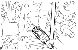
Using SST, install the sensor.
- SST
- 09817-33190
- Torque:
- 20 N*m { 204 kgf*cm, 15 ft.*lbf }
-
-
INSTALL CRANKSHAFT POSITION SENSOR
-
Install the sensor with the 2 bolts.
- Torque:
- 8.8 N*m { 90 kgf*cm, 78 in.*lbf }
-
Connect the sensor harness and install the clip.
-
-
INSTALL CAMSHAFT POSITION SENSOR
-
Install the sensor with the bolt.
- Torque:
- 8.8 N*m { 90 kgf*cm, 78 in.*lbf }
-
-
INSTALL INJECTOR ASSEMBLY
-
INSTALL NO. 1 NOZZLE LEAKAGE PIPE
-
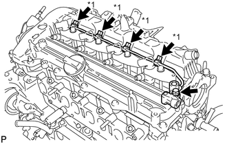
Text in Illustration *1 Union Bolt Install 4 new gaskets and the No. 1 nozzle leakage pipe with the 4 union bolts and bolt.
- Torque:
- for union bolt
- 18 N*m { 184 kgf*cm, 13 ft.*lbf }
- for bolt
- 21 N*m { 209 kgf*cm, 15 ft.*lbf }
-
-
INSTALL NO. 2 NOZZLE LEAKAGE PIPE
-
Temporarily install the No. 2 nozzle leakage pipe and a new gasket with the check valve and bolt.
-
Tighten the check valve.
- Torque:
- 32 N*m { 321 kgf*cm, 23 ft.*lbf }
-
Tighten the bolt.
- Torque:
- 32 N*m { 321 kgf*cm, 23 ft.*lbf }
-