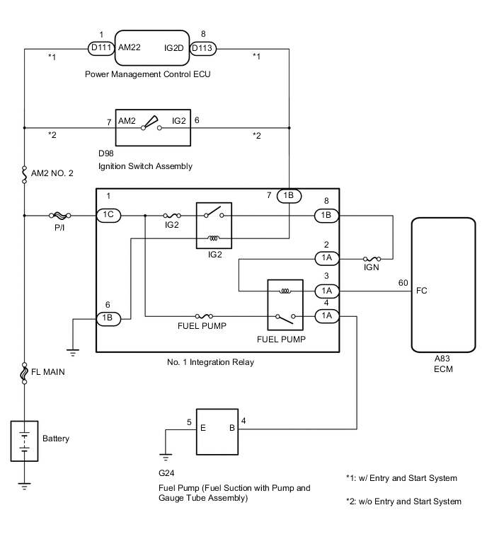
ECD SYSTEM Fuel Pump Control Circuit
DESCRIPTION
When the engine is cranked, the ST (Starter) relay drive signal is input to the STA terminal of the ECM, and the NE signal generated by the crankshaft position sensor is also input to the NE+ terminal. Thus, the ECM interprets that the engine has been cranked, current flows to the FUEL PUMP (Circuit Opening) relay, and the fuel pump (fuel suction with pump and gauge tube assembly) operates.
While the NE signal is input to the ECM with the engine running, the fuel pump operates continuously.
WIRING DIAGRAM
CAUTION / NOTICE / HINT
Note
-
When replacing the ECM, the ECM needs Registration and Initialization Click here.
-
Inspect the fuses for circuits related to this system before performing the following inspection procedure.
Tech Tips
-
When the ECM must be replaced, before replacing the ECM, perform the "Learning Values Save" function using the GTS. Then after installing the new ECM, perform all of the initialization/registrations for the "Learning Values Write" function by following the instructions shown on the GTS display.
-
Read freeze frame data using the GTS. Freeze frame data records the engine condition when malfunctions are detected. When troubleshooting, freeze frame data can help determine if the vehicle was moving or stationary, if the engine was warmed up or not, and other data from the time the malfunction occurred.
PROCEDURE
-
PERFORM ACTIVE TEST USING GTS (ACTUATOR TEST OF FPC)
-
Connect the GTS to the DLC3.
-
Turn the ignition switch to ON.
-
Turn the tester on.
-
Enter the following menus: Powertrain / Engine and ECT / Active Test / Actuator Test of FPC.
-
Check whether the fuel pump operating sound occurs when performing the Active Test on the tester.
Result Result Proceed to Fuel pump operating sound does not occur A Fuel pump operating sound occurs B
B 
PROCEED TO NEXT SUSPECTED AREA SHOWN IN PROBLEM SYMPTOMS TABLE Click here
A 
-
-
INSPECT NO. 1 INTEGRATION RELAY (FUEL PUMP)
-
Inspect the No. 1 integration relay Click here.
NG
REPLACE NO. 1 INTEGRATION RELAY
OK
-
-
CHECK HARNESS AND CONNECTOR (NO. 1 INTEGRATION RELAY - ECM)
-
Remove the No. 1 integration relay from the engine room No. 1 relay block.
-
Disconnect the ECM connector.
-
Measure the resistance according to the value(s) in the table below.
Standard Resistance Tester Connection Condition Specified Condition 1A-3 - A83-60 (FC) Always Below 1 Ω 1A-3 or A83-60 (FC) - Body ground Always 10 kΩ or higher
NG
REPAIR OR REPLACE HARNESS OR CONNECTOR
OK
-
-
CHECK HARNESS AND CONNECTOR (FUEL PUMP RELAY - IG2 RELAY)
-
Remove the No. 1 integration relay from the engine room No. 1 relay block.
-
Measure the resistance according to the value(s) in the table below.
Standard Resistance Tester Connection Condition Specified Condition 1A-2 - 1B-8 Always Below 1 Ω 1A-2 or 1B-8 - Body ground Always 10 kΩ or higher
NG
REPAIR OR REPLACE HARNESS OR CONNECTOR
OK
-
-
CHECK HARNESS AND CONNECTOR (NO. 1 INTEGRATION RELAY - FUEL SUCTION WITH PUMP AND GAUGE TUBE ASSEMBLY - BODY GROUND)
-
Remove the No. 1 integration relay from the engine room No. 1 relay block.
-
Disconnect the fuel pump (fuel suction with pump and gauge tube assembly) connector.
-
Measure the resistance according to the value(s) in the table below.
Standard Resistance Tester Connection Condition Specified Condition 1A-4 - G24-4 (B) Always Below 1 Ω G24-5 (E) - Body ground Always Below 1 Ω 1A-4 or G24-4 (B) - Body ground Always 10 kΩ or higher
NG
REPAIR OR REPLACE HARNESS OR CONNECTOR
OK
-
-
INSPECT FUEL PUMP (FUEL SUCTION WITH PUMP AND GAUGE TUBE ASSEMBLY)
-
Inspect the fuel pump (fuel suction with pump and gauge tube assembly) Click here.
OK
REPLACE ECM Click here
NG
REPLACE FUEL SUCTION WITH PUMP AND GAUGE TUBE ASSEMBLY Click here
-