ECD SYSTEM, Diagnostic DTC:P0122, P0123
| DTC Code | DTC Name |
|---|---|
| P0122 | Throttle/Pedal Position Sensor / Switch "A" Circuit Low |
| P0123 | Throttle / Pedal Position Sensor/Switch "A" Circuit High |
DESCRIPTION
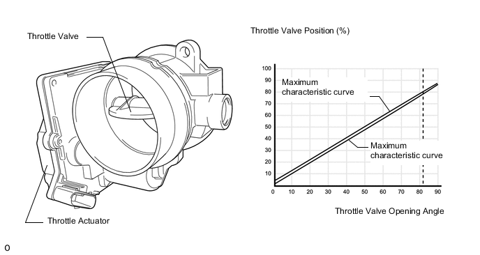
The ECM furnishes the 5-volt power and the ground connection for the throttle-valve actuator.
The ECM control unit opens and closes the throttle valve actuator electrically.
The exact current position of the throttle valve must be registered at all times in order to perform optimal control. This function is discharged by the throttle-valve sensor, which provides contactless monitoring of the throttle valve position within the throttle-valve actuator.
The electromotive throttle actuator is secured to the intake plenum.
A throttle valve is necessary for all diesel engines equipped with a particulate filter system. The throttle valve blocks the intake air to ensure that the necessary increased exhaust-gas temperatures required for regeneration of the particulate filter are reached.
The throttle-valve actuator closes when the ignition switch is turned off. This counteracts the tendency of the engine to vibrate during the shutdown phase. Another function is preventing the engine from overrevving.
When the ECD system detects increases in engine speed although no corresponding rises in the injection quantity have occurred, it responds by closing the throttle valve to limit engine speed.
| DTC No. | DTC Detection Condition | Trouble Area |
|---|---|---|
| P0122 | Throttle position sensor output (VTA1) is less than 0.15 V for 0.22 seconds. (3 trip detection logic) |
|
| DTC No. | DTC Detection Condition | Trouble Area |
|---|---|---|
| P0123 | Throttle position sensor output (VTA1) is more than 4.7 V for 0.22 seconds. (3 trip detection logic) |
|
| DTC No. | Data List |
|---|---|
| P0122 P0123 |
|
Tech Tips
Throttle position sensor output voltage "Throttle Sensor Volt %" is converted using 5 V = 100 %.
WIRING DIAGRAM
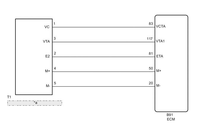
| *a | Diesel Throttle Body Assembly |
CAUTION / NOTICE / HINT
Note
When replacing the ECM, the ECM needs Registration and Initialization Click here.
Tech Tips
-
When the ECM must be replaced, before replacing the ECM, perform the "Learning Values Save" function using the GTS. Then after installing the new ECM, perform all of the initialization/registrations for the "Learning Values Write" function by following the instructions shown on the GTS display.
-
Read freeze frame data using the GTS. Freeze frame data records the engine condition when malfunctions are detected. When troubleshooting, freeze frame data can help determine if the vehicle was moving or stationary, if the engine was warmed up or not, and other data from the time the malfunction occurred.
PROCEDURE
-
CHECK HARNESS AND CONNECTOR (THROTTLE POSITION SENSOR - ECM)
-
Disconnect the diesel throttle body assembly connector.
-
Disconnect the ECM connector.
-
Measure the resistance according to the value(s) in the table below.
Standard Resistance Tester Connection Condition Specified Condition T1-1 (VC) - B91-83 (VCTA) Always Below 1 Ω T1-3 (VTA) - B91-117 (VTA1) Always Below 1 Ω T1-2 (E2) - B91-81 (ETA) Always Below 1 Ω T1-1 (VC) or B91-83 (VCTA) - Body ground Always 10 kΩ or higher T1-3 (VTA) or B91-117 (VTA1) - Body ground Always 10 kΩ or higher T1-2 (E2) or B91-81 (ETA) - Body ground Always 10 kΩ or higher
NG 
REPAIR OR REPLACE HARNESS OR CONNECTOR Click here
OK 
-
-
CHECK HARNESS AND CONNECTOR (VC VOLTAGE)
-
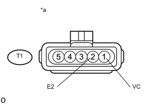
Text in Illustration *a Front view of wire harness connector
(to diesel throttle body assembly)
Disconnect the diesel throttle body assembly connector.
-
Measure the voltage according to the value(s) in the table below.
Standard Voltage Tester Connection Switch Condition Specified Condition T1-1 (VC) - T1-2 (E2) Ignition switch ON 4.5 to 5.5 V
NG
REPLACE ECM Click here
OK
-
-
REPLACE DIESEL THROTTLE BODY ASSEMBLY
-
Replace diesel throttle body assembly Click here.
NEXT
-
-
CHECK WHETHER DTC OUTPUT RECURS (DTC P0122 AND/OR P0123)
-
Connect the GTS to the DLC3.
-
Turn the ignition switch to ON and turn the GTS on.
-
Clear the DTCs Click here.
-
Turn the ignition switch off and wait for 60 seconds or more [A].
-
Perform road test [B].
-
Repeat [A] and [B] for the number of trips detected.
-
Enter the following menus: Powertrain / Engine and ECT / Trouble Codes.
-
Read the DTCs.
Result Result Proceed to No DTC output A DTC P0122 and/or P0123 B
A 
END
B
-
-
REPLACE ECM
-
Replace the ECM Click here.
NEXT
CONFIRM WHETHER MALFUNCTION HAS BEEN SUCCESSFULLY REPAIRED Click here
-
-
REPAIR OR REPLACE HARNESS OR CONNECTOR
-
Repair or replace the harness or connector.
NEXT
-
-
CONFIRM WHETHER MALFUNCTION HAS BEEN SUCCESSFULLY REPAIRED
-
Connect the GTS to the DLC3.
-
Turn the ignition switch to ON and turn the GTS on.
-
Clear the DTCs Click here.
-
Turn the ignition switch off and wait for 60 seconds or more [A].
-
Perform road test [B].
-
Repeat [A] and [B] for the number of trips detected.
-
Enter the following menus: Powertrain / Engine and ECT / Trouble Codes.
-
Confirm that the DTC is not output again.
NEXT
END
-