STEERING WHEEL INSTALLATION

PROCEDURE
-
INSTALL TRANSMISSION SHIFT SWITCH ASSEMBLY (w/ Shift Paddle Switch)
-
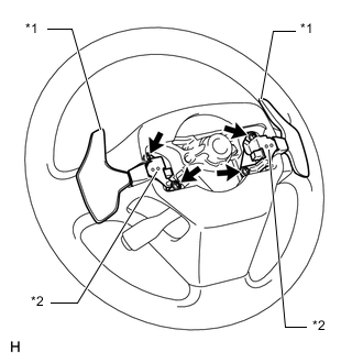
Text in Illustration *1 Shift Paddle Switch *2 Bracket Install the 2 shift paddle switches and 2 brackets with the 4 screws.
- Torque:
- 1.7 N*m { 17 kgf*cm, 15 in.*lbf }
CAUTION:
Make sure that the brackets are securely installed.
-
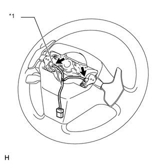
Text in Illustration *1 Switch Wire Connect the 2 switch wire connectors to the shift paddle switches.
-
Install the connector to the steering wheel assembly.
-
Install the clamp to the steering wheel assembly.
-
-
INSTALL STEERING SHAKE DAMPER
-
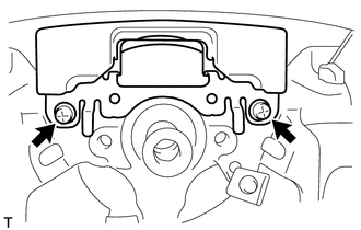
Install the steering shake damper with the 2 screws.
- Torque:
- 2.4 N*m { 24 kgf*cm, 21 in.*lbf }
-
-
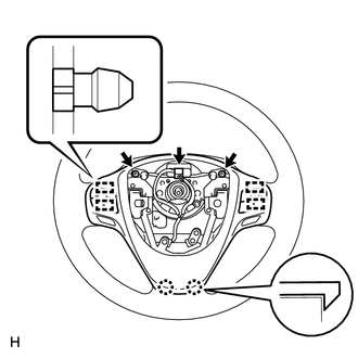
INSTALL STEERING PAD SWITCH ASSEMBLY
-
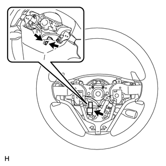
Attach the 2 claws and 4 pins to install the steering pad switch.
-
Install the 2 screws.
- Torque:
- 2.4 N*m { 24 kgf*cm, 21 in.*lbf }
-
Connect the connector.
-
-
INSTALL CRUISE CONTROL SWITCH WIRE (w/ Cruise Control System)
-
INSTALL CRUISE CONTROL MAIN SWITCH (w/ Cruise Control System)
-
PLACE FRONT WHEELS FACING STRAIGHT AHEAD
-
ADJUST SPIRAL CABLE
-
INSTALL STEERING WHEEL ASSEMBLY
-
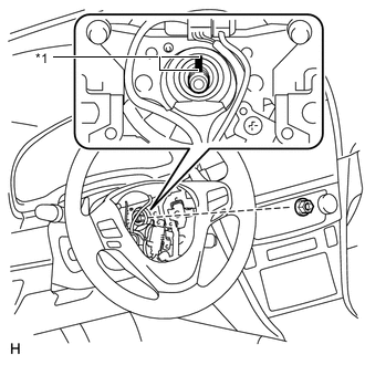
Text in Illustration *1 Matchmark Align the matchmarks on the steering wheel assembly and steering main shaft.
-
Install the steering wheel assembly set nut.
- Torque:
- 50 N*m { 510 kgf*cm, 37 ft.*lbf }
-
Connect the connectors to the spiral cable sub-assembly.
-
-
INSTALL STEERING PAD
-
INSTALL LOWER NO. 3 STEERING WHEEL COVER
-
INSTALL LOWER NO. 2 STEERING WHEEL COVER
-
INSPECT STEERING WHEEL CENTER POINT
-
CONNECT CABLE TO NEGATIVE BATTERY TERMINAL
Note
When disconnecting the cable, some systems need to be initialized after the cable is reconnected Click here.
-
INSPECT SRS WARNING LIGHT
-
Inspect the SRS warning light Click here.
-