POWER STEERING SYSTEM, Diagnostic DTC:C1551
| DTC Code | DTC Name |
|---|---|
| C1551 | IG Power Supply Voltage Malfunction |
DESCRIPTION
The power steering ECU determines whether the ignition switch status is ON or off through the IG power supply circuit.
| DTC Code | DTC Detection Condition | Trouble Area |
|---|---|---|
| C1551 | An IG power supply circuit malfunction inside the ECU. |
|
WIRING DIAGRAM
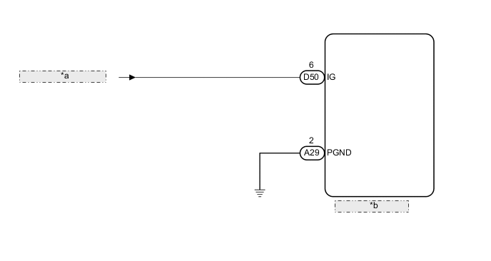
| *a | Stop and Start System |
| *b | Power Steering ECU |
CAUTION / NOTICE / HINT
Note
If the power steering ECU assembly is replaced with a new one, perform rotation angle sensor initialization and torque sensor zero point calibration Click here.
PROCEDURE
-
READ VALUE USING INTELLIGENT TESTER (IG POWER SUPPLY)
-
Turn the ignition switch off.
-
Connect the intelligent tester to the DLC3.
-
Turn the ignition switch to ON.
-
Turn the intelligent tester on.
-
Enter the following menus: Chassis / EMPS / Data List.
EMPS Tester Display Measurement Item/Range Normal Condition Diagnostic Note IG Power Supply ECU power source voltage/
Min.: 0.0000 V
Max.: 20.1531 V
11 to 14 V The ignition switch is ON. OK The normal condition value is displayed the intelligent tester. Result Result Proceed to OK for LHD A for RHD B NG C
A 
REPLACE POWER STEERING ECU ASSEMBLY Click here
B
REPLACE POWER STEERING ECU ASSEMBLY Click here
C 
-
-
CHECK HARNESS AND CONNECTOR (POWER STEERING ECU - BODY GROUND)
-
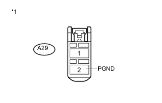
Text in Illustration *1 Front view of wire harness connector
(to Power Steering ECU)
Disconnect the A29 power steering ECU connector.
-
Measure the resistance according to the value(s) in the table below.
Standard Resistance Tester Connection Condition Specified Condition A29-2 (PGND) - Body ground Always Below 1 Ω
NG
REPAIR OR REPLACE HARNESS OR CONNECTOR
OK
-
-
CHECK HARNESS AND CONNECTOR (IG POWER SUPPLY)
-
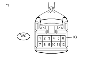
Text in Illustration *1 Front view of wire harness connector
(to Power Steering ECU)
Disconnect the D50 power steering ECU connector.
-
Measure the voltage according to the value(s) in the table below.
Standard Voltage Tester Connection Switch Condition Specified Condition D50-6 (IG) - Body ground Ignition switch ON 11 to 14 V Result Result Proceed to OK for LHD A for RHD B NG C
A
REPLACE POWER STEERING ECU ASSEMBLY Click here
B
REPLACE POWER STEERING ECU ASSEMBLY Click here
C
GO TO STOP AND START SYSTEM (HOW TO PROCEED WITH TROUBLESHOOTING) Click here
-