ELECTRIC PARKING BRAKE SYSTEM, Diagnostic DTC:C13A3/31, C13AB/33
| DTC Code | DTC Name |
|---|---|
| C13A3/31 | Open or Short in Lock Switch Circuit |
| C13AB/33 | Lock Switch Circuit |
DESCRIPTION
When the electric parking brake switch is pushed, a lock request signal is output to the electric parking brake ECU.
When the electric parking brake switch is pulled, a release request signal is output to the electric parking brake ECU.
| DTC Code | DTC Detection Condition | Trouble Area |
|---|---|---|
| C13A3/31 | Either condition is met:
|
|
| C13AB/33 | A malfunction occurs in the electric parking brake switch. |
WIRING DIAGRAM
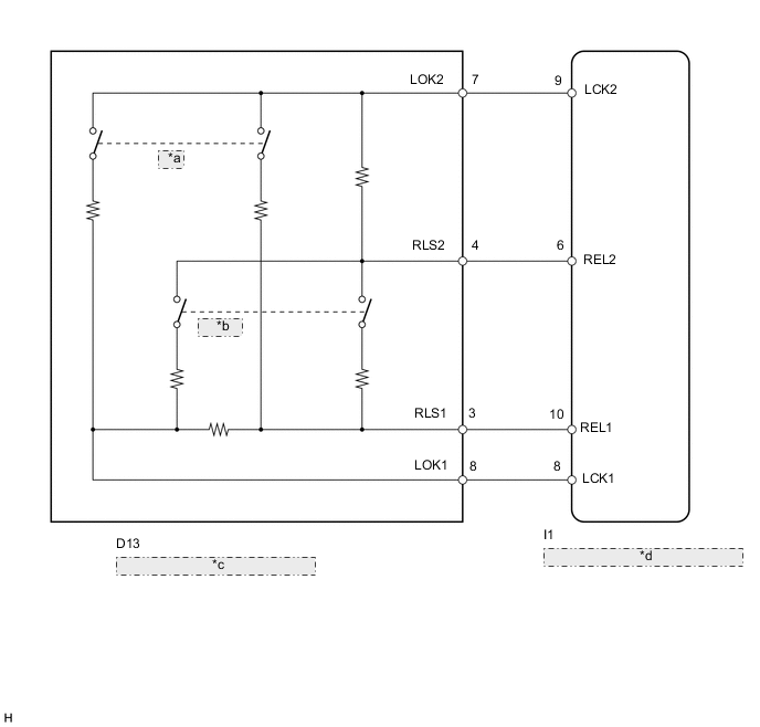
| *a | Lock |
| *b | Release |
| *c | Electric Parking Brake Switch |
| *d | Electric Parking Brake ECU (Parking Brake with Actuator Assembly) |
CAUTION / NOTICE / HINT
Note
-
Before performing work, turn the ignition switch off and wait approximately 20 seconds to make sure that the parking brake cannot operate.
-
When replacing the parking brake with bracket actuator assembly, perform zero point calibration Click here.
PROCEDURE
-
INSPECT ELECTRIC PARKING BRAKE SWITCH
-
Remove the electric parking brake switch Click here.
-
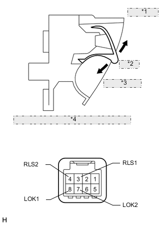
*1 Pulled (Release) *2 Neutral *3 Pushed (Lock) *4 Component without harness connected: (Electric Parking Brake Switch) Measure the resistance according to the value(s) in the table below.
Standard Resistance Tester Connection Switch Condition Specified Condition 8 (LOK1) - 7 (LOK2) Neutral 1M Ω or higher Pushed (Lock) 1.29 k to 1.32 kΩ Pulled (Release) 3.87 k to 3.96 kΩ 3 (RLS1) - 4 (RLS2) Neutral 1M Ω or higher Pushed (Lock) 3.48 k to 3.56 kΩ Pulled (Release) 1.36 k to 1.40 kΩ 7 (LOK2) - 4 (RLS2) Always 2.58 k to 2.64 kΩ 7 (LOK2) - 3 (RLS1) Neutral 1M Ω or higher Pushed (Lock) 890 to 920 Ω Pulled (Release) 3.95 k to 4.03 kΩ 4 (RLS2) - 8 (LOK1) Neutral 1M Ω or higher Pushed (Lock) 3.87 k to 3.96 kΩ Pulled (Release) 1.29 k to 1.32 kΩ 3 (RLS1) - 8 (LOK1) Neutral 2.58 k to 2.64 kΩ Pushed (Lock) 1.40 k to 1.44 kΩ Pulled (Release) 1.53 k to 1.57 kΩ
NG 
REPLACE ELECTRIC PARKING BRAKE SWITCH Click here
OK 
-
-
CHECK HARNESS AND CONNECTOR (ELECTRIC PARKING BRAKE SWITCH - ELECTRIC PARKING BRAKE ECU)
-
Disconnect the electric parking brake switch connector.
-
Disconnect the electric parking brake ECU connector.
-
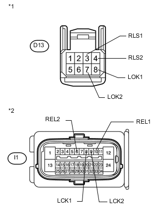
Text in Illustration *1 Front view of wire harness connector
(to Electric Parking Brake Switch)
*2 Front view of wire harness connector
(to Electric Parking Brake ECU)
Measure the resistance according to the value(s) in the table below.
Standard Resistance Tester Connection Condition Specified Condition D13-3 (RLS1) - I1-10 (REL1) Always Below 1 Ω D13-3 (RLS1) - Body ground Always 100 kΩ or higher D13-4 (RLS2) - I1-6 (REL2) Always Below 1 Ω D13-4 (RLS2) - Body ground Always 100 kΩ or higher D13-7 (LOK2) - I1-9 (LCK2) Always Below 1 Ω D13-7 (LOK2) - Body ground Always 100 kΩ or higher D13-8 (LOK1) - I1-8 (LCK1) Always Below 1 Ω D13-8 (LOK1) - Body ground Always 100 kΩ or higher
NG
REPAIR OR REPLACE HARNESS OR CONNECTOR
OK
-
-
RECONFIRM DTC
-
Clear the DTCs Click here.
-
Operate the electric parking brake switch.
-
Check for DTCs Click here.
Result Result Proceed to DTC is output. A DTC is not output. B
A
REPLACE PARKING BRAKE WITH BRACKET ACTUATOR ASSEMBLY Click here
B
USE SIMULATION METHOD TO CHECK Click here
-