ELECTRIC PARKING BRAKE SYSTEM, Diagnostic DTC:C13A2/22
| DTC Code | DTC Name |
|---|---|
| C13A2/22 | Engine / Power Switch Malfunction |
DESCRIPTION
When the ignition switch is turned to ON, an ignition signal is sent to the electric parking brake ECU through the CAN communication line and direct line.
This DTC is stored when the ignition signals from the CAN communication line and direct line do not match.
| DTC Code | DTC Detection Condition | Trouble Area |
|---|---|---|
| C13A2/22 | The ignition signals sent through the CAN communication line and direct line do not match. |
|
WIRING DIAGRAM
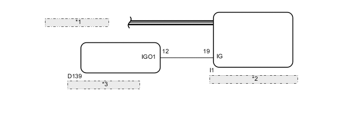
| *1 | CAN Communication Line |
| *2 | Electric Parking Brake ECU (Parking Brake with Bracket Actuator Assembly) |
| *3 | Engine Stop and Start ECU |
CAUTION / NOTICE / HINT
Note
-
Before performing work, turn the ignition switch off and wait approximately 20 seconds to make sure that the parking brake cannot operate.
-
When replacing the parking brake with bracket actuator assembly, perform zero point calibration Click here.
PROCEDURE
-
CHECK DTC (CAN COMMUNICATION SYSTEM)
-
Check for DTCs Click here.
Result Result Proceed to CAN DTC is not output. A CAN DTC is output. B
B 
GO TO CAN COMMUNICATION SYSTEM (HOW TO PROCEED WITH TROUBLESHOOTING) Click here
A 
-
-
CHECK HARNESS AND CONNECTOR (IG TERMINAL)
-
Disconnect the I1 electric parking brake ECU connector.
-
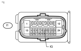
Text in Illustration *1 Front view of wire harness connector
(to Electric Parking Brake ECU)
Measure the voltage according to the value(s) in the table below.
Standard Voltage Tester Connection Switch Condition Specified Condition I1-19 (IG) - Body ground Ignition switch ON 9.5 to 14 V
NG
INSPECT STOP AND START SYSTEM (BACKUP BOOST CONVERTER CIRCUIT) Click here
OK
-
-
RECONFIRM DTC
-
Clear the DTCs Click here.
-
Check for DTCs Click here.
Result Result Proceed to DTC is output. A DTC is not output. B
A
REPLACE PARKING BRAKE WITH BRACKET ACTUATOR ASSEMBLY Click here
B
USE SIMULATION METHOD TO CHECK Click here
-