BRAKE BOOSTER INSTALLATION
PROCEDURE
-
TEMPORARILY INSTALL BRAKE MASTER CYLINDER PUSH ROD CLEVIS
-
Install the lock nut and brake master cylinder push rod clevis to the brake booster assembly.
Tech Tips
Tighten the lock nut after adjusting the brake pedal height.
-
-
INSTALL BRAKE BOOSTER GASKET
-
Install a new brake booster gasket to the brake booster assembly.
-
-
INSTALL BRAKE BOOSTER ASSEMBLY
-
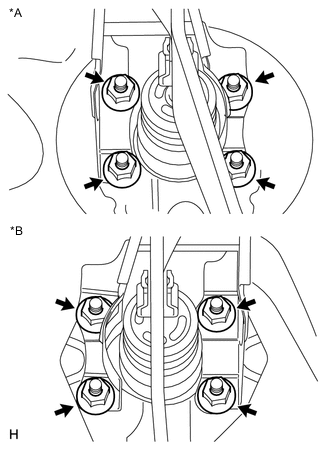
Text in Illustration *A for LHD *B for RHD Install the brake booster assembly to the body with the 4 nuts.
- Torque:
- 13 N*m { 130 kgf*cm, 9 ft.*lbf }
Note
Do not damage the brake lines or fuel lines.
-
-
INSTALL FRONT BRAKE LINE
-
for LHD:
-
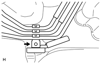
Install a new clamp and the brake tube to the brake actuator bracket.
-
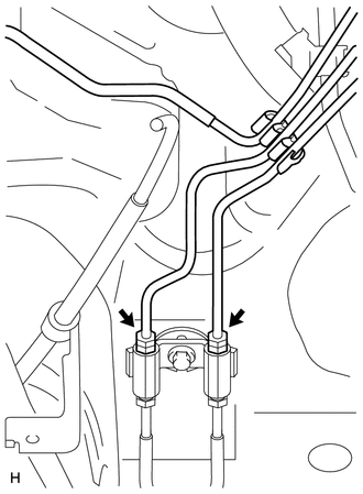
Using a union nut wrench, connect the 2 brake tubes to the 2-way.
- Torque:
- 15 N*m { 155 kgf*cm, 11 ft.*lbf }
Note
Use the formula to calculate special torque values for situations where a union nut wrench is combined with a torque wrench Click here.
-
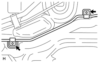
Install 2 new clamps and the brake tube to the body.
-
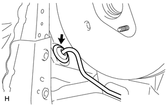
Attach the grommet to install the brake tube to the body.
-
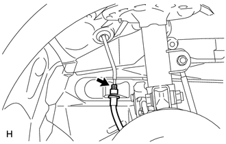
Using a union nut wrench, connect the brake tube to the front brake flexible hose RH.
- Torque:
- 15 N*m { 155 kgf*cm, 11 ft.*lbf }
Note
Use the formula to calculate special torque values for situations where a union nut wrench is combined with a torque wrench Click here.
-
Using a union nut wrench, connect the brake tube to the front brake flexible hose LH.
- Torque:
- 15 N*m { 155 kgf*cm, 11 ft.*lbf }
Note
Use the formula to calculate special torque values for situations where a union nut wrench is combined with a torque wrench Click here.
-
Install the clamp with the bolt.
- Torque:
- 8.0 N*m { 82 kgf*cm, 71 in.*lbf }
-
-
for RHD:
-
Attach a new clamp and the brake tube to the brake actuator bracket.
-
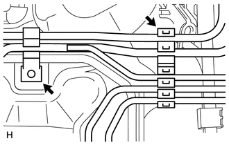
Install a new clamp and the brake tube to the body.
-
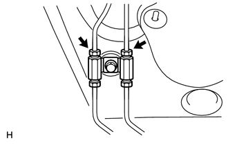
Using a union nut wrench, connect the 2 brake tubes to the 2-way.
- Torque:
- 15 N*m { 155 kgf*cm, 11 ft.*lbf }
Note
Use the formula to calculate special torque values for situations where a union nut wrench is combined with a torque wrench Click here.
-
Install a new clamp and the brake tube to the body.
-
Attach the grommet to install the brake tube to the body.
-
Using a union nut wrench, connect the brake tube to the front flexible hose RH.
- Torque:
- 15 N*m { 155 kgf*cm, 11 ft.*lbf }
Note
Use the formula to calculate special torque values for situations where a union nut wrench is combined with a torque wrench Click here.
-
Using a union nut wrench, connect the brake tube to the front flexible hose LH.
- Torque:
- 15 N*m { 155 kgf*cm, 11 ft.*lbf }
Note
Use the formula to calculate special torque values for situations where a union nut wrench is combined with a torque wrench Click here.
-
Install the clamp with the bolt.
- Torque:
- 8.0 N*m { 82 kgf*cm, 71 in.*lbf }
-
-
-
INSTALL CHECK VALVE GROMMET
-
Install a new check valve grommet to the brake booster assembly.
-
-
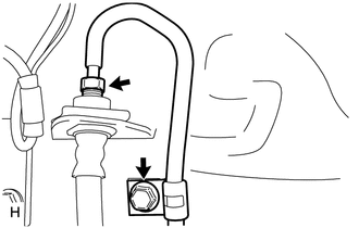
INSTALL BRAKE VACUUM CHECK VALVE ASSEMBLY
-
Install the vacuum check valve assembly to the brake booster assembly.
-
-
CONNECT VACUUM HOSE
-
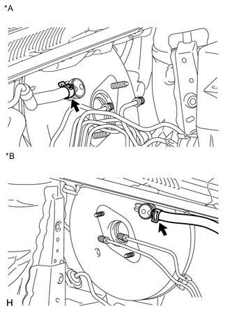
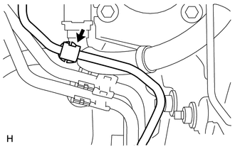
Text in Illustration *A for LHD *B for RHD Connect the vacuum hose with the clip.
-
-
CONNECT PUSH ROD PIN
-
INSTALL BRAKE PEDAL RETURN SPRING
-
INSTALL BRAKE MASTER CYLINDER SUB-ASSEMBLY
-
Install the brake master cylinder sub-assembly Click here.
-
-
INSTALL BRAKE ACTUATOR ASSEMBLY (for LHD)
-
Install the brake actuator assembly Click here.
-
-
INSTALL ENGINE ASSEMBLY
-
for 1WW:
-
for 2WW:
-
-
FILL RESERVOIR WITH BRAKE FLUID
-
BLEED BRAKE MASTER CYLINDER
-
BLEED BRAKE LINE
-
BLEED CLUTCH LINE (for 1WW, 2WW)
-
INSPECT FOR BRAKE FLUID LEAK
-
INSPECT FLUID LEVEL
-
INSTALL FRONT WHEEL
- Torque:
- 103 N*m { 1050 kgf*cm, 76 ft.*lbf }
-
INSPECT AND ADJUST BRAKE PEDAL HEIGHT
-
INSPECT BRAKE PEDAL FREE PLAY
-
INSPECT BRAKE PEDAL RESERVE DISTANCE