ECD SYSTEM(w/o Gear Shift Indicator) Rough Idling or Excessive Engine Vibrations
DESCRIPTION
| Malfunction Condition | Main Trouble Area | Related Trouble Area |
|---|---|---|
|
|
|
Tech Tips
-
Rough idling and excessive engine vibrations are checked in this troubleshooting procedure.
-
Specified values in the following troubleshooting flowchart are for reference only. Variations in the Data List result values may occur depending on the measuring conditions or the vehicle age. Do not judge the vehicle to be normal even when the Data List values indicate a standard level. There are possibly some concealed factors of the malfunction.
-
Check that the vehicle has not been modified in any way prior to the vehicle inspection.
-
Faults and Symptoms of Common Rail Diesel Components
-
Engine Control
Mass Air Flow Meter Component Mass air flow meter Main fault Decrease in performance (foreign matter is stuck) Symptoms Lack of power, black smoke Data List MAF Tech Tips
The maximum fuel injection volume is controlled according to the output from the mass air flow meter.
Glow System Component Glow system Main fault Open circuit, glow plug relay fault Symptoms Difficult to start, rough idle, knocking, white smoke (when cold) Data List Check the glow plug indicator light Diagnostic Point Try to measure the resistance of the glow plug Engine Component Engine Main fault Loss of compression Symptoms Rough idle (lack of power always) Data List Engine Speed of Cyl
-
When cranking during the "Check the Cylinder Compression" Active Test, if there is a high speed cylinder, approx. 100 rpm more than the other cylinders, that cylinder may lose compression.
Injection Feedback Val
-
If Injection Feedback Val is more than 3 mm3/st, the cylinder may have a fault.
-
-
Diesel Injection
Fuel Supply Pump Component Fuel supply pump Main fault - Symptoms Difficult to start, engine stalling, rough idle, lack of power Data List Fuel Press, Target Common Rail Pressure, Target Pump SCV Current
-
At a stable condition (e.g. Idling), Fuel Press is within +/-5000 kPa of "Target Common Rail Pressure".
-
If the fuel pressure is 20000 kPa below the target pressure then a lack of power will be felt.
-
If the fuel pressure is below 25000 kPa then idling will be rough.
Tech Tips
-
The fuel pressure changes at engine starting, but is approx. 25000 kPa at engine start after the engine is warmed up.
-
When Target Pump SCV Current is 3000 mA or more, the suction control valve has a tendency to become stuck.
Diagnostic Trouble Code Even if Fuel Press is less than Target Common Rail Pressure, a DTC will not be stored. Fuel Filter Component Fuel filter Main fault Blockage Symptoms Difficult to start, engine stalling, rough idle, lack of power Data List Fuel Press, Target Common Rail Pressure
-
At a stable condition (e.g. Idling), the fuel pressure is within +/-5000 kPa of "Target Common Rail Pressure".
-
If the fuel pressure is 20000 kPa below the target pressure then a lack of power will be felt.
-
If the fuel pressure is below 25000 kPa then idling will be rough.
Tech Tips
The fuel pressure changes at engine starting, but is approx. 25000 kPa at engine start after the engine is warmed up.
Diagnostic Trouble Code Even if Fuel Press is less than Target Common Rail Pressure, a DTC will not be stored. Fuel Injector Component Fuel injector Main fault Blockage Symptoms Rough idle, lack of power, black smoke, white smoke, knocking Data List Injection Feedback Val
-
When an Injection Feedback Val is more than 3 mm3/st, the cylinder is not normal. This can be read after idling for 1 minute with the engine warmed up (engine coolant temperature is more than 70°C (158°F)).
Pressure Discharge Valve Component Pressure discharge valve Main fault Does not completely close Symptoms Difficult to start, engine stall, rough idle, lack of power Injector Driver (EDU) Component Injector Driver (EDU) Main fault Circuit fault: The fuel injector does not open. Symptoms Difficult to start, rough idle, lack of power, black smoke, white smoke, knocking Data List Same as fuel injector Diagnostic Trouble Code When the EDU has a fault, some DTCs may be stored. Fuel Pressure Sensor Component Fuel pressure sensor Main fault Open circuit, decrease in performance (foreign matter is stuck) Symptoms Difficult to start, rough idle, engine stall, lack of power Data List Fuel Press, Target Common Rail Pressure
-
Slowly raise the engine speed from idling to 3000 rpm with the vehicle stopped, and check that Fuel Press follows Target Common Rail Pressure. If the fuel pressure sensor malfunctions, the actual fuel pressure may deviate from the target fuel pressure (however, the value may not deviate even when a malfunction is present).
Diagnostic Trouble Code When the fuel pressure sensor has a fault, some DTCs may be stored. Irregular Fuel Component Irregular fuel Main fault - Symptoms Difficult to start, rough idle (especially when cold) -
-
Diesel EGR
EGR System Component EGR system Main fault
-
Does not move smoothly
-
Does not close completely
Symptoms
-
Rough idle
-
EGR valve stuck closed: A loud turbocharger sound.
-
EGR valve stuck open: Difficult to start (does not stall), black smoke, lack of power (if there is an excess in the quantity of EGR and there is a heavy load, when the vehicle starts moving, a lack of power will be felt).
Data List Actual EGR Valve Pos., Target EGR Pos.
-
Generally, Actual EGR Valve Pos. = Target EGR Pos. +/-5% (fully closed 0%, fully open 100%).
-
Using EGR valve Active Test, check whether Actual EGR Valve Pos. follows Target EGR Pos. (the engine coolant temperature and intake air temperature should be considered when a malfunction occurs).
-
EGR valve is fully closed when the ignition switch is turned to ON (engine stopped).
-
EGR valve opens to the halfway point at idling after the engine is warmed up.
EGR Close Lrn. Val., EGR Close Lrn. Status
-
When leaving the vehicle idling, when EGR Close Lrn. Status is OK, the normal range of EGR Close Lrn. Val. is 0.34 to 0.70 V.
-
In cases when EGR Close Lrn. Status. is NG or EGR Close Lrn. Val. is out of the normal range (0.34 to 0.70 V), it is possible that the EGR valve cannot completely close.
-
-
Diesel Throttle
Diesel Throttle System Component Diesel throttle system Main fault Stuck, does not move smoothly Symptoms
-
Stuck closed: Lack of power, difficult to start, rough idle, engine stall, black smoke. These may occur when stuck almost fully closed.
-
Stuck open: Turbocharger sound increases. When the engine is stopped, engine vibrations may occur.
Data List
-
Actual Throttle Position
0%: Fully open
100%: Fully closed
-
When the ignition switch is ON (the engine is stopped), the diesel throttle is fully open. When idling, the diesel throttle is at the halfway point. When the ignition switch is turned from ON to off, the throttle is temporarily closed fully.
-
-
-
Data List Related to Rough Idling
Note
The Data List values in the table are the results of checking one vehicle under a specific condition (engine coolant temperature, intake air temperature, atmospheric pressure etc.). Therefore, use these values for reference only.
-
Engine Control
Engine Speed Data List Judgment of Data List Values Faulty Component Diagnosis Note Engine Speed Idling: 720 to 820 rpm Crankshaft position sensor When the crankshaft position sensor is malfunctioning, "Engine Speed" is approximately 0 or varies greatly from the actual engine speed. MAF Data List Judgment of Data List Values Faulty Component Diagnosis Note MAF -
-
MAF meter
-
MAF meter circuit
-
Intake system clogging, leaking
-
Exhaust system clogging
-
Turbocharger sub-assembly
-
Leaking or clogging of turbocharger passages
-
EGR valve does not close
-
Based on the MAF, the ECM controls the fuel injection volume, injection timing, EGR, etc.
-
If the value is always approximately 0 g/sec.:
-
Mass air flow meter power source circuit is open.
-
VG circuit is open or shorted.
-
If the value is always 200 g/sec. or more:
-
EVG circuit is open.
Results of real-vehicle check:
-
Ignition switch ON: 0 g/sec.
-
Cranking: 5.07 g/sec.
-
Idling (warm up the engine): 3.87 g/sec. (2 minutes after starting the vehicle)
-
Running without load (2500 rpm): 34 g/sec.
-
Driving with the accelerator fully open at 2000 rpm: 79 g/sec.
-
Driving with the accelerator fully open at 3000 rpm: 138 g/sec.
Tech Tips
The maximum fuel injection volume is controlled according to the output from the mass air flow meter.
Intake Air Data List Judgment of Data List Values Faulty Component Diagnosis Note Intake Air - Intake air temperature sensor.
-
After a long soak, the engine coolant temperature, intake air temperature and ambient air temperature are approximately equal.
-
If the value is -40°C (-40°F) or 140°C (284°F), the sensor circuit is open or shorted.
Coolant Temp Data List Judgment of Data List Values Faulty Component Diagnosis Note Coolant Temp
-
Engine coolant temperature is approximately equal to intake air temperature after leaving overnight. After warm-up: Engine coolant temperature is 60°C (140°F) or higher.
-
In cases when the engine coolant temperature output is obviously higher than the actual engine coolant temperature, when it is cold, there will be difficulty starting due to problems with glow plugs or insufficient fuel injection.
-
In cases when the engine coolant temperature sensor output is obviously lower than the actual engine coolant temperature, when it is warm, there will be difficulty starting (black smoke will also occur) due to an excess of injected fuel.
Engine coolant temperature sensor
-
If the value is -40°C (-40°F) or 140°C (284°F), the sensor circuit is open or shorted.
-
After a long soak, the coolant temperature, intake air temperature and ambient air temperature are approximately equal.
Engine Speed of Cyl #1 (to #4) Data List Judgment of Data List Values Faulty Component Diagnosis Note Engine Speed of Cyl #1 (to #4) When cranking, the engine speed of each cylinder is the same under normal conditions. When a cylinder is approximately 100 rpm higher than the other cylinders, it is conceivable that the compression of that cylinder is being lost.
Tech Tips
This data is output only when the Active Test "Check the Cylinder Compression" is performed.
-
-
Output only when the Active Test "Check the Cylinder Compression" is performed.
-
With this Active Test, the fuel injection is stopped.
-
Indicates the speed of each cylinder when cranking.
Example - Normal: "Engine speed" of all cylinders is approximately equal.
No. 1 cylinder compression low: "Engine speed of Cyl#1" = approximately 300 rpm, "Engine speed of Cyl #2 to #4 cylinder" = approximately 200 rpm.
-
-
Diesel Injection
Target Common Rail Pressure Data List Judgment of Data List Values Faulty Component Diagnosis Note Target Common Rail Pressure - -
-
Inspect the (actual) fuel pressure, comparing it against the common rail target value.
-
Considered normal when the actual fuel pressure is within +/-5000 kPa of the target fuel pressure under stable conditions.
Results of real-vehicle check:
-
Ignition switch ON: 35000 kPa
-
Cranking: 50000 kPa
-
Idling (warm up the engine): 35000 kPa (2 minutes after starting the vehicle)
-
Running without load (2500 rpm): 63240 kPa
-
Running without load (3500 rpm): 72950 kPa
-
Driving with the accelerator fully open at 2000 rpm: 138590 kPa
-
Driving with the accelerator fully open at 3000 rpm: 183210 kPa
Fuel Press Data List Judgment of Data List Values Faulty Component Diagnosis Note Fuel Press
-
In a stable operating condition (e.g. idling), Fuel Press is Target Common Rail Pressure +/-5000 kPa.
-
During cranking, if Fuel Press is lower than 25000 kPa, there may be difficulty starting (take care as there is a response lag when the pressure rises).
-
When Fuel Press is lower than 25000 kPa, rough idling will occur.
-
If there is a fault with the fuel supply pump (lack of discharge quantity) or pressure discharge valve (will not fully close), the fuel pressure will drop. Also, a blocked fuel filter, leakage from fuel pipes, and lack of fuel will also make the fuel pressure drop.
-
If air mixes with the fuel, the fuel pressure will shift away from the target fuel pressure.
-
When there is a fault with the fuel supply pump, there is a possibility of lack of power, engine stall, rough idle and difficulty starting.
-
Fuel press is the actual common rail fuel pressure.
-
Inspect by comparing Fuel Press with Target Common Rail Pressure.
-
The ECM uses Fuel Press for feedback control of Target Fuel Pressure via the supply pump.
The injection amount is determined based on the injection timing and fuel pressure.
Also, the spray pattern is selected based on the fuel pressure.
Results of real-vehicle check:
-
Ignition switch ON: 0 kPa
-
Cranking: 35390 kPa
-
Idling (warm up the engine): 33640 kPa (2 minutes after starting the vehicle)
-
Running without load (2500 rpm): 62920 kPa
-
Driving with the accelerator fully open at 2000 rpm: 134390 kPa
-
Driving with the accelerator fully open at 3000 rpm: 178670 kPa
Target Pump SCV Current Data List Judgment of Data List Values Faulty Component Diagnosis Note Target Pump SCV Current Idling after warming up: roughly 923 to 1123 mA. When this value is large, the pump is trying to increase the fuel discharge rate.
-
With this data, component fault not specified, use this data as a reference.
-
If the current is 3000 mA or more, there is a possibility the suction control valve is stuck.
-
ECU-calculated value for the suction control valve actuation target current.
-
Value is large when a high fuel pressure is desired.
-
When this deviates from the standard value, it indicates that for some reason, even though the pump is running hard, the actual fuel pressure is inconsistent with the target fuel pressure.
Results of real-vehicle check:
-
Ignition switch ON: 1008 mA
-
Cranking: 1155 mA
-
Running without load (2500 rpm): 1300 mA
-
Driving with the accelerator fully open at 2000 rpm: 1233 mA
-
Driving with the accelerator fully open at 3000 rpm: 1397 mA
Injection Feedback Val #1 (to #4) Data List Judgment of Data List Values Faulty Component Diagnosis Note Injection Feedback Val #1 (to #4)
-
When idling after the engine is warmed up, the fuel quantity of each fuel injector is corrected to make each cylinder engine speed equal.
-
Cylinders more than 3 mm3/st may have a fault.
Tech Tips
Read the value after one minute of idling after warm up (engine coolant temperature above 70°C (158°F)). This value is only calculated when idling.
-
Fault with a fuel injector or lack of compression of a cylinder with a large Injection Feedback Val.
-
Do a compression Active Test. If there is a cylinder that is around 100 rpm more than the other cylinders, there is a possibility that the compression of that cylinder is being lost.
-
If all the cylinder speeds are even according to the compression Active Test result, the fuel injector of the cylinder may have a fault.
-
With fuel injector faults, other than difficulty starting, there is a possibility of rough idling, lack of power, black smoke, white smoke and knocking.
-
When idling after warm up, the injection amount for each cylinder is corrected to optimize the difference of each cylinder engine speed.
Example: For cylinders that are slowing the engine speed compared to other cylinders, the injection volume is increased.
-
"Injection Feedback Val" more than 3.0 mm3/st: Injector breakdown or insufficient compression is causing poor combustion.
Injection Volume Data List Judgment of Data List Values Faulty Component Diagnosis Note Injection Volume - - After warming up the engine, when Injection Volume during idling is 10 mm3/st or more, there is tendency for the injector to clog.
Results of real-vehicle check:
-
Cranking: 22 mm3/st (Note: Varies depending on coolant temperature)
-
Idling (warm up the engine): 5 mm3/st
-
Running without load (2500 rpm): 8 mm3/st
-
Running without load (4700 rpm): 16 mm3/st
-
Driving with the accelerator fully open at 2000 rpm: 75 mm3/st
-
Driving with the accelerator fully open at 3000 rpm: 78 mm3/st
-
-
Diesel Throttle
Actual Throttle Position Data List Judgment of Data List Values Faulty Component Diagnosis Note Actual Throttle Position
-
When the ignition switch is turned to ON (engine stopped), the diesel throttle is fully open. When the ignition switch is turned from ON to off, the diesel throttle is fully closed temporarily.
-
With the diesel throttle stuck almost fully closed, there is a possibility of rough idling, engine stall, black smoke, difficulty starting and lack of power.
Diesel throttle body Actual Throttle Position is the closing percentage of the throttle valve.
-
Fully closed: 100%
-
Fully open: 0%
Tech Tips
There is no connection with the accelerator. However, under full load, the throttle is usually fully open (0%).
Results of real-vehicle check:
-
Ignition switch ON: 0%
-
Cranking: -6%
-
Idling (warm up the engine): 93%
-
Running without load (2500 rpm): 51%
-
Driving with the accelerator fully open at 2000 rpm: 0%
-
Driving with the accelerator fully open at 3000 rpm: 0%
-
-
Diesel EGR
Target EGR Position Data List Judgment of Data List Values Faulty Component Diagnosis Note Target EGR Position - -
-
Fully open: 100%
-
Fully closed: 0%
-
Used for comparison to "Actual EGR Valve Pos".
Results of real-vehicle check:
-
Ignition switch ON: 0%
-
Cranking: 0%
-
Idling (warm up the engine): 54%
-
Running without load (2500 rpm): 47%
-
Driving with the accelerator fully open at 2000 rpm: 0%
-
Driving with the accelerator fully open at 3000 rpm: 0%
Actual EGR Valve Pos. Data List Judgment of Data List Values Faulty Component Diagnosis Note Actual EGR Valve Pos.
-
Generally Actual EGR Valve Pos. = Target EGR Pos. (Fully closed = 0%, Fully open = 100%)
-
The EGR valve Active Test can be used to check whether the Actual EGR Valve Pos. = Target EGR Pos.
EGR valve assembly
-
Inspect while comparing to "Target EGR Valve Pos.".
-
Sometimes the malfunction only occurs around a certain temperature, so refer to the engine coolant temperature and outside temperature at the time the malfunction occurred.
Results of real-vehicle check:
-
Ignition switch ON: 0%
-
Cranking: 0%
-
Idling (warm up the engine): 54%
-
Running without load (2500 rpm): 47%
-
Driving with the accelerator fully open at 2000 rpm: 0%
-
Driving with the accelerator fully open at 3000 rpm: 0%
EGR Close Lrn. Status Data List Judgment of Data List Values Faulty Component Diagnosis Note EGR Close Lrn. Status
-
"OK" means the fully closed position learning has completed normally.
-
When NG, the learned fully closed position may be outside of the normal range.
- After disconnecting and reconnecting the battery cable, if the ignition switch has not been turned off once, learning may not be completed. EGR Close Lrn. Val. Data List Judgment of Data List Values Faulty Component Diagnosis Note EGR Close Lrn. Val. When leaving the vehicle idling, with the EGR Close Lrn. Status OK, the normal range of EGR Close Lrn. Val. is within 0.34 to 0.70 V. In cases when EGR Close Lrn. Status is NG or EGR Close Lrn. Val. is at the maximum or minimum (0.34 to 0.70 V) of the normal range, it is possible that the EGR valve is not completely closed or a foreign object is lodged in the EGR valve seat area. -
-
This value is the EGR position sensor output voltage.
-
As the maximum and minimum settings are 0.34 V and 0.70 V, if the value becomes stuck at either of these, there is a malfunction in the lift sensor or the valve position is shifted (due to foreign matter, etc.).
-
-
-
Actual Examples of Malfunction
Tech Tips
-
The purpose of the following examples is help you to understand the relationship between each Data List item when a certain malfunction occurs. Understanding this relationship helps you to find the real root cause easier.
-
The following are examples of actual malfunctions of a common rail diesel engine.
-
Use them for reference when diagnosing malfunctions.
-
These are not data of the AVENSIS 2AD-FTV.
-
Supply pump malfunction (suction control valve momentarily sticking)
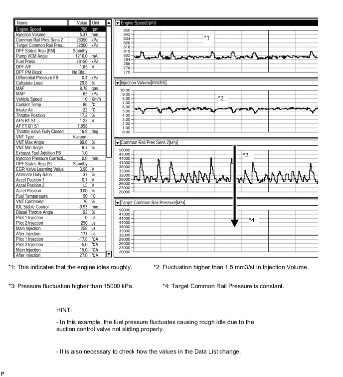
-
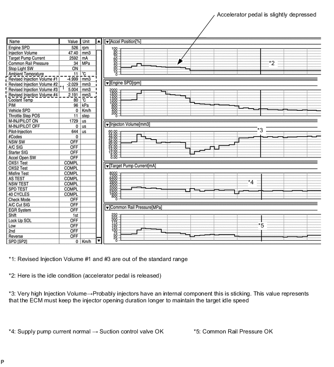
Fuel injectors sticking
-
CAUTION / NOTICE / HINT
Note
-
After replacing the fuel supply pump, the ECM needs initialization Click here.
-
After replacing a fuel injector, the ECM needs registration Click here.
Tech Tips
Before troubleshooting, conduct the following:
-
(a) Check the fuel quality.
-
(b) Check the fuel for air.
-
(c) Check the fuel system for blockages.
-
(d) Check the air filter.
-
(e) Check the engine oil.
-
(f) Check the engine coolant.
-
(g) Check the engine idling speed and maximum engine speed.
-
(h) Check the vacuum pump.
PROCEDURE
-
CHECK MALFUNCTION CONDITION
-
Identify when shuddering occurs.
Result Result Proceed to When idling A When engaging engine clutch at vehicle start B
(Clutch system shudders)
B 
REPAIR OR REPLACE CLUTCH SYSTEM
A 
-
-
CHECK WIRE HARNESS AND CONNECTION IN ENGINE COMPARTMENT
-
Check the wire harness and connector connections of common rail system components.
OK The wire harnesses and connectors are connected securely.
NG
REPAIR OR REPLACE HARNESS OR CONNECTOR
OK
-
-
READ OUTPUT DTC (RELATING TO ENGINE)
-
Connect the intelligent tester to the DLC3.
-
Turn the ignition switch to ON and turn the tester on.
-
Enter the following menus: Powertrain / Engine and ECT / DTC.
-
Read pending DTCs.
Result Result Proceed to No DTCs are output A Engine related DTCs are output B
B
GO TO DTC CHART Click here
A
-
-
TAKE SNAPSHOT DURING IDLING AND 3000 rpm
-
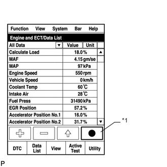
*1 Snapshot Button Connect the intelligent tester to the DLC3.
-
Start the engine and turn the tester on.
-
Enter the following menus: Powertrain / Engine and ECT / Data List / All Data.
-
Take a snapshot of the following Data List items.
Tech Tips
-
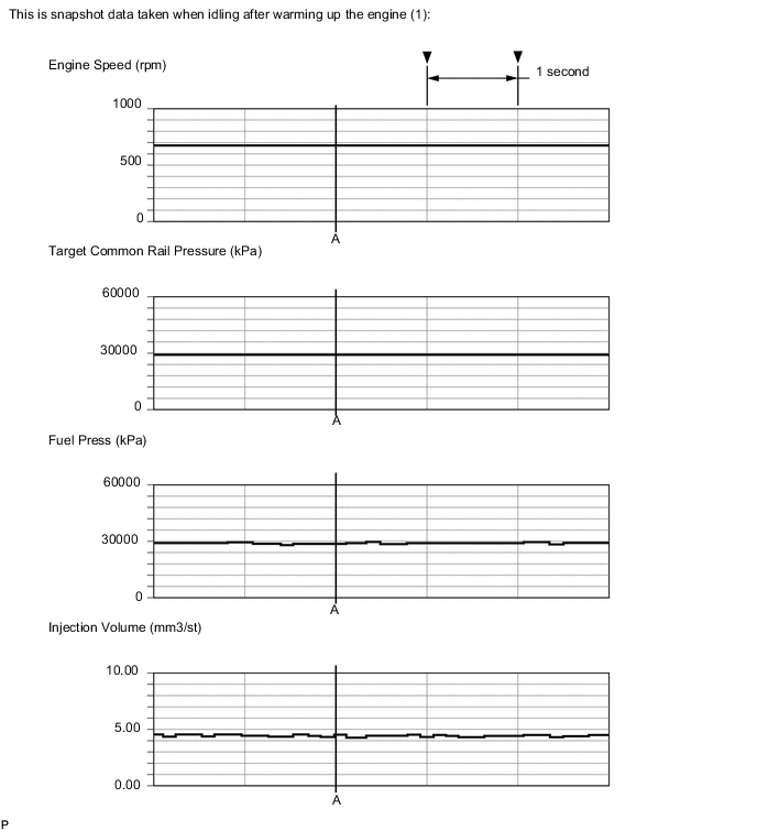
A snapshot can be used to compare vehicle data from the time of the malfunction to normal data and is very useful for troubleshooting. The data in the list below is that of a normal vehicle, but as the data varies between individual vehicles, this data should only be used for reference.
-
Graphs like the ones shown below can be displayed by transferring the stored snapshot data from the tester to a PC. Intelligent Viewer must be installed on the PC.
-
Check the Data List at idling and at 3000 rpm with no load after the engine is warmed up.
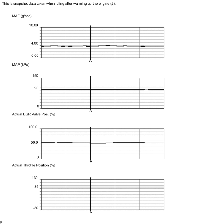
Data Condition Idling (Engine Warmed Up) Data List Value Unit Engine Speed 771 rpm MAP 94 kPa MAF 3.87 g/sec Target Common Rail Pressure 35000 kPa Fuel Press 33640 kPa Injection Volume 5.15 mm3/st
VN Turbo Command 57 % Target EGR Position 54.1 % Actual EGR Valve Pos. 54.1 % EGR Close Lrn. Val. 0.52 V EGR Close Lrn. Status OK - Actual Throttle Position 93 % Throttle Close Learning Val. 16.9 deg Diesel Throttle Learn Status OK - Accel Position 0.00 % Injection Feedback Val #1 0.0 mm3/st
Injection Feedback Val #2 -0.5 mm3/st
Injection Feedback Val #3 0.0 mm3/st
Injection Feedback Val #4 0.1 mm3/st
Atmosphere Pressure 100 kPa Coolant Temp 76 °C Calculate Load 14.5 % Pilot 1 Injection Period 208 μs Pilot 2 Injection Period 213 μs Data Condition at 3000 rpm (Engine Warmed Up) Data List Value Unit Engine Speed 3000 rpm Target Booster Pressure 115.46 kPa MAP 121 kPa MAF 52.51 g/sec Target Common Rail Pressure 67500 kPa Fuel Press 67460 kPa Target Pump SCV Current 1039.0 mA Injection Volume 8.73 mm3/st
VN Turbo Command 62 % Target EGR Position 42.3 % Actual EGR Valve Pos. 42.3 % EGR Close Lrn. Val. 0.52 V EGR Close Lrn. Status OK - Actual Throttle Position 40 % Throttle Close Learning Val. 16.9 deg Diesel Throttle Learn Status OK - Accel Position 14.06 % Injection Feedback Val #1 0.0 mm3/st
Injection Feedback Val #2 -0.5 mm3/st
Injection Feedback Val #3 0.1 mm3/st
Injection Feedback Val #4 0.0 mm3/st
Coolant Temp 83 °C Calculate Load 20.7 % Pilot 1 Injection Period 163 μs Pilot 2 Injection Period 182 μs -
NEXT
-
-
CHECK SNAPSHOT (FUEL PRESS AND TARGET COMMON RAIL PRESSURE)
-
*1 Snapshot Button Check Fuel Press and Target Common Rail Pressure in the snapshot taken when the engine was idling.
Result Result Proceed to Fuel Press is within +/-5000 kPa of Target Common Rail Pressure. A Fuel Press is outside range of +/-5000 kPa from Target Common Rail Pressure. B
B 
BLEED AIR FROM FUEL SYSTEM Click here
A
-
-
CHECK SNAPSHOT (TARGET PUMP SCV CURRENT)
-
*1 Snapshot Button Check Target Pump SCV Current in the snapshot taken when the engine was idling and at 3000 rpm with no load.
Result Result Proceed to Target Pump SCV Current is less than 3000 mA A Target Pump SCV Current is 3000 mA or higher B
B
CHECK HARNESS AND CONNECTOR (SUCTION CONTROL VALVE - ECM) Click here
A
-
-
CHECK FUEL INJECTOR COMPENSATION CODE
-
Read the fuel injector compensation codes Click here.
OK Compensation codes stored in the ECM match the compensation codes of the installed fuel injectors.
NG
REGISTER INJECTOR COMPENSATION CODE AND PERFORM PILOT QUANTITY LEARNING Click here
OK
-
-
CHECK SNAPSHOT (INJECTION FEEDBACK VAL #1 to #4)
-
*1 Snapshot Button Check Injection Feedback Val # and Injection Volume in the snapshot taken after the engine is warmed up and has been idling for 1 minute.
Tech Tips
The shift lever should be in neutral and the A/C switch and all accessory switches should be off.
Result Result Proceed to Injection Feedback Val #1 to #4 is within the range of +/-3 mm3/st and Injection Volume is 10 mm3/st or less
A Injection Feedback Val #1 to #4 is within the range of +/-3 mm3/st and Injection Volume is more than 10 mm3/st
B* Injection Feedback Val #1 to #4 is outside the range of +/-3 mm3/st
Tech Tips
There may be a malfunction in the corresponding cylinder.
B Tech Tips
*: When case "B" occurs, usually symptoms may be noticeable, such as difficult starting, rough idling, knocking or black smoke at high common rail pressure.
B
PERFORM ACTIVE TEST USING INTELLIGENT TESTER (CONTROL THE CYLINDER #1 TO #4 FUEL CUT) Click here
A
-
-
CHECK TEMPERATURE WHEN ROUGH IDLING TROUBLE OCCURS
-
Check the temperature when rough idling trouble occurs.
Result Result Proceed to Rough idling only for cold engine. A Rough idling both for cold and warmed up engine. B
B
CHECK EGR VALVE ASSEMBLY Click here
A
-
-
INSPECT ENGINE COOLANT TEMPERATURE SENSOR
-
After engine completely warmed up, allow engine to soak for long time (8 hours or more).
-
Connect the intelligent tester to the DLC3.
-
Turn the ignition switch to ON and turn the tester on.
-
Enter the following menus: Powertrain / Engine and ECT / Data List / Coolant temp.
-
Read the value.
OK The difference between the displayed value and outside air temperature is below 5°C (9°F).
NG
REPLACE ENGINE COOLANT TEMPERATURE SENSOR Click here
OK
-
-
INSPECT GLOW PLUG ASSEMBLY
-
Inspect the glow plug assembly Click here.
NG
REPLACE GLOW PLUG ASSEMBLY Click here
OK
-
-
CHECK EGR VALVE ASSEMBLY
-
Connect the intelligent tester to the DLC3.
-
Turn the ignition switch to ON and turn the tester on.
-
Enter the following menus: Powertrain / Engine and ECT / Data List / EGR Close Lrn. Status.
-
Read the values.
Standard EGR Close Lrn. Status is OK -
Enter the following menus: Powertrain / Engine and ECT / Active Test / Control the EGR Step Position.
-
When changing the Active Test continuously value to 0, 30, 60, 90, 60, 30 and 0%, check that Actual EGR Valve Pos. smoothly changes to the set opening angle.
OK Value smoothly changes to set opening angle. -
Remove the EGR valve assembly Click here.
-
Visually check the electric EGR control valve for deposits.
If there are deposits, clean the electric EGR control valve.
Note
-
When cleaning the electric EGR control valve, make sure the valve is completely closed.
-
Do not forcibly open the valve, as it may be damaged or deformed.
-
When cleaning the electric EGR control valve, use a piece of cloth soaked with cleaning solvent. Spraying the solvent directly onto these parts or soaking the parts in the solvent may damage the parts.
-
-
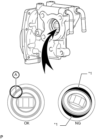
*1 Gap Hold the electric EGR control valve up to a light, and then from the side indicated by the arrow in the illustration, visually check that there is no gap between the valve and body.
OK No light passes through (there is no gap between the valve and body). If light passes through (there is a gap between the valve and body), replace the electric EGR control valve assembly.
Tech Tips
Light passes through part A shown in the illustration even if the valve is completely closed, this is not a problem.
NG
REPLACE EGR VALVE ASSEMBLY Click here
OK
-
-
CHECK DIESEL THROTTLE BODY ASSEMBLY
-
Connect the intelligent tester to the DLC3.
-
Turn the ignition switch to ON and turn the tester on.
-
Enter the following menus: Powertrain / Engine and ECT / Active Test / Diesel Throttle Target Angle.
-
When changing the Active Test continuously value to 0, 30, 60, 90, 60, 30 and 0%, check that Actual Throttle Position smoothly changes to the set opening angle.
OK Value smoothly changes to set opening angle.
NG
REPLACE DIESEL THROTTLE BODY Click here
OK
-
-
RESET ECM
-
Disconnect the cable from the negative (-) battery terminal for at least 2 minutes.
-
Reconnect the cable to the negative (-) battery terminal.
-
Check whether the malfunction has been successfully repaired by performing a driving test.
OK Malfunction has been repaired successfully.
OK
CHECK FOR INTERMITTENT PROBLEMS
NG
-
-
BASIC INSPECTION
-
Check the fuel quality.
-
Check the fuel for air.
-
Check the fuel system for blockages.
-
Check the air filter.
-
Check the engine oil.
-
Check the engine coolant.
-
Check the engine idling speed and maximum engine speed.
-
Check the vacuum pump.
OK Each inspection result is normal.
NG
REPAIR OR REPLACE MALFUNCTIONING PARTS
OK
-
-
CHECK ENGINE MOUNTING INSULATOR
-
Visually check that the engine mounting insulator is installed correctly and is not crooked or twisted.
OK No abnormalities.
NG
REPAIR OR REPLACE ENGINE MOUNTING INSULATOR
OK
-
-
CHECK INTAKE SYSTEM DEPOSIT
-
Check carbon has accumulated on the intake manifold, cylinder head, etc. and if so, clean it off.
NEXT
-
-
CONFIRM WHETHER MALFUNCTION HAS BEEN SUCCESSFULLY REPAIRED
Tech Tips
Symptoms may have appeared due to carbon deposits, etc.
NEXT
END
-
BLEED AIR FROM FUEL SYSTEM
-
Bleed the air from the fuel system Click here.
NEXT
-
-
CHECK AND REPLACE FUEL INLET LINE
-
Check the following items, and repair or replace the malfunctioning part if necessary.
-
Check for fuel filter clogging.
-
Check for fuel freezing in the fuel line.
-
Check for clogging or leaks in the fuel pipe and hose between the fuel tank and fuel supply pump.
-
NEXT
-
-
CONFIRM WHETHER MALFUNCTION HAS BEEN SUCCESSFULLY REPAIRED
OK
END
NG
REPLACE SUCTION CONTROL VALVE Click here
-
CHECK HARNESS AND CONNECTOR (SUCTION CONTROL VALVE - ECM)
-
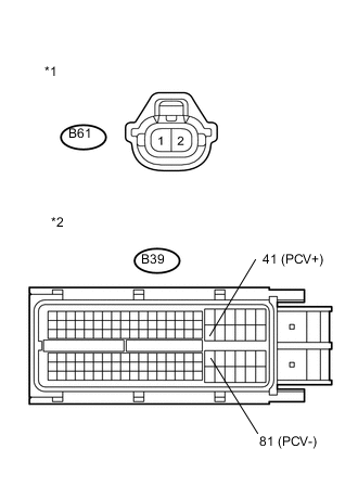
Text in Illustration *1 Front view of wire harness connector
(to Suction Control Valve)
*2 Front view of wire harness connector
(to ECM)
Disconnect the suction control valve connector.
-
Disconnect the ECM connector.
-
Measure the resistance according to the value(s) in the table below.
Standard Resistance (Check for Open) Tester Connection Condition Specified Condition B61-1 (+B) - B39-41 (PCV+) Always Below 1 Ω B61-2 (PCV) - B39-81 (PCV-) Always Below 1 Ω Standard Resistance (Check for Short) Tester Connection Condition Specified Condition B61-1 (+B) or B39-41 (PCV+) - Body ground Always 10 kΩ or higher B61-2 (PCV) or B39-81 (PCV-) - Body ground Always 10 kΩ or higher -
Reconnect the suction control valve connector.
-
Reconnect the ECM connector.
NG
REPAIR OR REPLACE HARNESS OR CONNECTOR
OK
-
-
CHECK IF FUEL IS BEING SUPPLIED TO FUEL SUPPLY PUMP
-
Disconnect the inlet hose from the fuel supply pump.
-
Operate the priming pump and check that fuel is being supplied to the fuel supply pump.
OK Fuel is properly supplied to the fuel supply pump when the priming pump is operated. Tech Tips
-
When lack of fuel, fuel pressure drops.
-
Inspect for fuel filter clogging.
(Check that the fuel filter is not clogged)
-
NG
CHECK AND REPLACE CLOGGED FUEL PIPE (INCLUDING FUEL FREEZING) (FUEL TANK - FUEL SUPPLY PUMP) Click here
OK
-
-
REPLACE SUCTION CONTROL VALVE
-
Replace the suction control valve Click here.
NEXT
-
-
BLEED AIR FROM FUEL SYSTEM
-
Bleed the air from the fuel system Click here.
NEXT
-
-
PERFORM FUEL SUPPLY PUMP INITIALIZATION
-
Perform fuel supply pump initialization Click here.
NEXT
-
-
READ VALUE USING INTELLIGENT TESTER (FUEL PRESS AND TARGET COMMON RAIL PRESSURE)
-
Connect the intelligent tester to the DLC3.
-
Start the engine.
-
Turn the tester on.
-
Enter the following menus: Powertrain / Engine and ECT / Data List / Target Common Rail Pressure and Fuel Press.
-
Check that the fuel pressure of the common rail is within the specification below.
OK Fuel Press is within +/-5000 kPa of Target Common Rail Pressure when engine is idling and running at 3000 rpm without load.
NG
REPLACE COMMON RAIL Click here
OK
-
-
CONFIRM WHETHER MALFUNCTION HAS BEEN SUCCESSFULLY REPAIRED
NEXT
END
-
REPLACE COMMON RAIL
-
Replace the common rail Click here.
NEXT
-
-
BLEED AIR FROM FUEL SYSTEM
-
Bleed the air from the fuel system Click here.
NEXT
-
-
CONFIRM WHETHER MALFUNCTION HAS BEEN SUCCESSFULLY REPAIRED
NEXT
END
-
PERFORM ACTIVE TEST USING INTELLIGENT TESTER (CONTROL THE CYLINDER #1 TO #4 FUEL CUT)
Tech Tips
Use this Active Test to determine the malfunctioning cylinder.
-
Connect the intelligent tester to the DLC3.
-
Start the engine and turn the tester on.
-
Enter the following menus: Powertrain / Engine and ECT / Active Test / Control the Cylinder #1 to #4 Fuel Cut.
Tech Tips
-
If the engine idle speed does not change when a fuel injector is disabled, the cylinder being tested is malfunctioning. Record any malfunctioning cylinders.
-
If the cylinder being tested is normal, there will be a significant change in idle speed when the fuel injection is stopped for that cylinder.
-
NEXT
-
-
PERFORM ACTIVE TEST USING INTELLIGENT TESTER (CHECK THE CYLINDER COMPRESSION)
Tech Tips
Use this Active Test to help determine whether a cylinder has compression loss or not.
-
Connect the intelligent tester to the DLC3.
-
Start the engine and turn the tester on.
-
Enter the following menus: Powertrain / Engine and ECT / Active Test / Check the Cylinder Compression / Data List / Compression / Engine Speed of Cyl #1 to #4.
-
Check the engine speed during the Active Test.
Result Result Proceed to The values of Engine Speed Cyl #1 to #4 are within +/-10 rpm of each other. B Except above A Tech Tips
When cranking, if the speed of a cylinder is approximately 100 rpm more than the other cylinders, there is probably a complete loss of compression in that cylinder.
B
REPLACE INJECTOR OF MALFUNCTIONING CYLINDER Click here
A
-
-
CHECK CYLINDER COMPRESSION PRESSURE OF MALFUNCTIONING CYLINDER
-
Check cylinder compression pressure Click here.
NG
CHECK ENGINE TO DETERMINE CAUSE OF LOW COMPRESSION
OK
-
-
REPLACE INJECTOR OF MALFUNCTIONING CYLINDER
-
Replace the fuel injector Click here.
NEXT
-
-
BLEED AIR FROM FUEL SYSTEM
-
Bleed the air from the fuel system Click here.
NEXT
-
-
REGISTER INJECTOR COMPENSATION CODE AND PERFORM PILOT QUANTITY LEARNING
-
Register the injector compensation codes Click here.
-
Perform the fuel injector pilot quantity learning Click here.
NEXT
-
-
CONFIRM WHETHER MALFUNCTION HAS BEEN SUCCESSFULLY REPAIRED
NEXT
END
-
CHECK AND REPLACE CLOGGED FUEL PIPE (INCLUDING FUEL FREEZING) (FUEL TANK - FUEL SUPPLY PUMP)
-
Check and replace clogged the fuel pipe.
NEXT
-
-
BLEED AIR FROM FUEL SYSTEM
-
Bleed the air from the fuel system Click here.
NEXT
-
-
CONFIRM WHETHER MALFUNCTION HAS BEEN SUCCESSFULLY REPAIRED
NEXT
END