ECD SYSTEM(w/o Gear Shift Indicator) Engine Difficult to Start or Stalling
DESCRIPTION
-
Faults and Symptoms of Common Rail Diesel Components
-
Engine Control
Mass Air Flow Meter Component Mass air flow meter Main fault Decrease in performance (foreign matter is stuck) Symptoms Lack of power, black smoke Data List MAF Tech Tips
The maximum fuel injection volume is controlled according to the output from the mass air flow meter.
Intake System Component Intake system Symptom: Main fault
-
Lack of power (No black smoke): air filter blockage, air duct is crushed/leaking
-
Black smoke (No lack of power): Leakage between the turbo and intake manifold
Data List
-
MAP (inside intake air pressure)
-
Target Booster Pressure
When the accelerator is fully depressed, if MAP is 20 kPa lower than Target Booster Pressure for more than 5 seconds then a lack of power will be felt.
Turbocharger System Component Turbocharger system Main fault
-
Air leak in the turbocharged air passage
-
Turbo motor driver not operating well
-
Turbocharger (turbine, bearing)
Symptoms Lack of power (when vehicle starting, when heavy load)
(Black smoke is not emitted when racing while vehicle stopped)
Data List MAP (inside intake air pressure), Target Booster Pressure
-
When the accelerator is fully depressed, if MAP is 20 kPa lower than Target Booster Pressure for more than 5 seconds then a lack of power will be felt.
-
With the ignition switch ON or during idling, MAP = atmospheric pressure (standard atmospheric pressure = 101 kPa). When the engine speed is about 1500 rpm or more, the turbocharger starts to take effect and MAP becomes higher than atmospheric pressure.
-
Atmospheric pressure increases 1 kPa each time altitude increases by 100 m, and is also affected by the current weather conditions.
VN Turbo Command
-
0%: Vanes fully open (drive rod contracts)
-
Over 90%: Vanes fully closed (drive rod expands and turbo operates effectively)
Diagnostic Point
-
Using the Active Test "Test the Turbo Charger Step Motor", check the drive rod movement.
-
Check the drive rod movement when the ignition switch is turned from ON to off.
Exhaust System Component Exhaust system Main fault Blockage Symptoms Lack of power (high engine speed, when heavy load) Data List MAP (inside intake air pressure)
When the accelerator is fully depressed, if MAP is 20 kPa lower than Target Booster Pressure for more than 5 seconds then a lack of power will be felt.
Glow System Component Glow system Main fault Open circuit, glow plug relay fault Symptoms Difficult to start, rough idle, knocking, white smoke (when cold) Data List Check the glow plug indicator light Diagnostic Point Try to measure the resistance of the glow plug Battery Component Battery Main fault Battery is depleted Symptoms Difficult to start (cannot crank, crank speed is low), horn is quiet. Data List Battery Voltage
When cranking, battery voltage is less than 5 V
Engine - 1 Component Engine Main fault Damaged, seized up Symptoms Cannot crank, crank speed is low, strange noise Engine - 2 Component Engine Main fault Loss of compression Symptoms Rough idle (lack of power always) Data List Engine Speed of Cyl
-
When cranking during the "Check the Cylinder Compression" Active Test, if there is a high speed cylinder, approx. 100 rpm more than the other cylinders, that cylinder may lose compression.
Injection Feedback Val
-
If Injection Feedback Val is more than 3 mm3/st, the cylinder may have a fault.
Start System Component Entry and start system Main fault Starter system malfunction Symptoms Difficult to start Data List Starter Signal
-
Ignition switch (STA) operation
ON: Starter is operating
OFF: Starter is not operating
Immobiliser system Component Engine immobiliser system Main fault Engine immobiliser system (w/ Entry and Start System) / Problem Symptoms Table Click here
Engine immobiliser system (w/o Entry and Start System) / Problem Symptoms Table Click here
Symptoms Engine does not start Data List Immobiliser Communication
-
ON: Normal
-
OFF: GND short or immobiliser is set
Engine Immobiliser System (w/ Entry and Start System) / Data List Click here
Engine Immobiliser System (w/o Entry and Start System) / Data List Click here
-
-
Diesel Injection
Fuel Supply Pump Component Fuel supply pump Main fault - Symptoms Difficult to start, engine stalling, rough idle, lack of power Data List Fuel Press, Target Common Rail Pressure, Target Pump SCV Current
-
At a stable condition (e.g. Idling), Fuel Press is within +/-5000 kPa of "Target Common Rail Pressure".
-
If the fuel pressure is 20000 kPa below the target pressure then a lack of power will be felt.
-
If the fuel pressure is below 25000 kPa then idling will be rough.
Tech Tips
-
The fuel pressure changes at engine starting, but is approx. 25000 kPa at engine start after the engine is warmed up.
-
When Target Pump SCV Current is 3000 mA or more, the suction control valve has a tendency to become stuck.
Diagnostic Trouble Code Even if Fuel Press is less than Target Common Rail Pressure, a DTC will not be stored. Fuel Filter Component Fuel filter Main fault Blockage Symptoms Difficult to start, engine stalling, rough idle, lack of power Data List Fuel Press, Target Common Rail Pressure
-
At a stable condition (e.g. Idling), the fuel pressure is within +/-5000 kPa of "Target Common Rail Pressure ".
-
If the fuel pressure is 20000 kPa below the target pressure then a lack of power will be felt.
-
If the fuel pressure is below 25000 kPa then idling will be rough.
Tech Tips
The fuel pressure changes at engine starting, but is approx. 25000 kPa at engine start after the engine is warmed up.
Diagnostic Trouble Code Even if Fuel Press is less than Target Common Rail Pressure, a DTC will not be stored. Fuel Injector Component Fuel injector Main fault Blockage Symptoms Rough idle, lack of power, black smoke, white smoke, knocking Data List Injection Feedback Val
-
When an Injection Feedback Val is more than 3 mm3/st, the cylinder is not normal. This can be read after idling for 1 minute with the engine warmed up (engine coolant temperature is more than 70°C (158°F)).
Pressure Discharge Valve Component Pressure discharge valve Main fault Does not completely close Symptoms Difficult to start, engine stall, rough idle, lack of power Injector Driver (EDU) Component Injector Driver (EDU) Main fault Circuit fault: The fuel injector does not open. Symptoms Difficult to start, rough idle, lack of power, black smoke, white smoke, knocking Data List Same as fuel injector Diagnostic Trouble Code When the EDU has a fault, some DTCs may be stored. Fuel Pressure Sensor Component Fuel pressure sensor Main fault Open circuit, decrease in performance (foreign matter is stuck) Symptoms Difficult to start, rough idle, engine stall, lack of power Data List Fuel Press, Target Common Rail Pressure
-
Slowly raise the engine speed from idling to 3000 rpm with the vehicle stopped, and check that Fuel Press follows Target Common Rail Pressure. If the fuel pressure sensor malfunctions, the actual fuel pressure may deviate from the target fuel pressure. (However, the value may not deviate even when a malfunction is present).
Diagnostic Trouble Code When the fuel pressure sensor has a fault, some DTCs may be stored. Irregular Fuel Component Irregular fuel Main fault - Symptoms Difficult to start, rough idle (especially when cold) -
-
Diesel EGR
EGR System Component EGR system Main fault
-
Does not move smoothly
-
Does not close completely
Symptoms
-
Rough idle
-
EGR valve stuck closed: A loud turbocharger sound.
-
EGR valve stuck open: Difficult to start (does not stall), black smoke, lack of power (if there is an excess in the quantity of EGR and there is a heavy load, when the vehicle starts moving, a lack of power will be felt).
Data List Actual EGR Valve Pos., Target EGR Pos.
-
Generally, Actual EGR Valve Pos. = Target EGR Pos. +/-5% (fully closed 0%, fully open 100%).
-
Using EGR valve Active Test, check whether Actual EGR Valve Pos. follows Target EGR Pos. (the engine coolant temperature and intake air temperature should be considered when a malfunction occurs).
-
EGR valve is fully closed when the ignition switch is turned to ON (engine stopped).
-
EGR valve opens to the halfway point at idling after the engine warmed up.
EGR Close Lrn. Val., EGR Close Lrn. Status
-
When leaving the vehicle idling, when EGR Close Lrn. Status is OK, the normal range of EGR Close Lrn. Val. is 0.34 to 0.70 V.
-
In cases when EGR Close Lrn. Status. is NG or EGR Close Lrn. Val. is out of the normal range (0.34 to 0.70 V), it is possible that the EGR valve cannot completely close.
-
-
Diesel Throttle
Diesel Throttle System Component Diesel throttle system Main fault Stuck, does not move smoothly Symptoms
-
Stuck closed: Lack of power, difficult to start, rough idle, engine stall, black smoke. These may occur when stuck almost fully closed.
-
Stuck open: Turbocharger sound increases. When the engine is stopped, engine vibrations may occur.
Data List
-
Actual Throttle Position
0%: Fully open
100%: Fully closed
-
When the ignition switch is ON (the engine is stopped), the diesel throttle is fully open. When idling, the diesel throttle is at the halfway point. When the ignition switch is turned from ON to off, the throttle is temporarily closed fully.
-
-
-
Data List Related to Starting Trouble
Note
The Data List values in the table are the results of checking one vehicle under a specific condition (engine coolant temperature, intake air temperature, atmospheric pressure etc.). Therefore, use these values for reference only.
-
Engine Control
MAP Data List Judgment of Data List Values Faulty Component Diagnosis Note MAP
-
When MAP is low, there will be difficulty starting.
-
With ignition switch ON or during idling, MAP is nearly equal to Atmosphere Pressure (standard atmospheric pressure = 101 kPa).
When MAP is low, the following conditions are possible:
-
Diesel throttle nearly fully closed.
-
Intake system blocked (turbocharger system also).
-
Exhaust system blocked.
-
When the ignition switch is ON or the vehicle is idling, MAP (intake manifold absolute pressure) and Atmosphere Pressure are approximately equal (standard atmospheric pressure = 101 kPa).
Above approx. 1500 rpm, the turbo becomes effective, and the pressure becomes higher than atmospheric pressure.
-
Inspect while comparing with "Target Booster Pressure".
-
With the accelerator fully open, if the actual Manifold Absolute Pressure (MAP) is low compared to the target booster pressure by at least 20 kPa for 5 seconds or more, a feeling of insufficient power will occur.
Results of real-vehicle check:
-
Ignition switch ON: 100 kPa
-
Cranking: 99 kPa
-
Idling (warm up the engine): 94 kPa (2 minutes after starting the vehicle)
-
Running without load (2500 rpm): 117 kPa
-
Driving with the accelerator fully open at 2000 rpm: 186 kPa
-
Driving with the accelerator fully open at 3000 rpm: 242 kPa
MAF Data List Judgment of Data List Values Faulty Component Diagnosis Note MAF -
-
MAF meter
-
MAF meter circuit
-
Intake system clogging, leaking
-
Exhaust system clogging
-
Turbocharger sub-assembly
-
Leaking or clogging of turbocharger passages
-
EGR valve does not close
-
Based on the MAF, the ECM controls the fuel injection volume, injection timing, EGR, etc.
-
If the value is always approximately 0 g/sec.:
-
Mass air flow meter power source circuit is open.
-
VG circuit is open or shorted.
-
If the value is always 200 g/sec. or more:
-
EVG circuit is open.
Results of real-vehicle check:
-
Ignition switch ON: 0 g/sec.
-
Cranking: 5.07 g/sec.
-
Idling (warm up the engine): 3.87 g/sec. (2 minutes after starting the vehicle)
-
Running without load (2500 rpm): 34 g/sec.
-
Driving with the accelerator fully open at 2000 rpm: 79 g/sec.
-
Driving with the accelerator fully open at 3000 rpm: 138 g/sec.
Tech Tips
The maximum fuel injection volume is controlled according to the output from the mass air flow meter.
Intake Air Data List Judgment of Data List Values Faulty Component Diagnosis Note Intake Air - Intake air temperature sensor.
-
After a long soak, the engine coolant temperature, intake air temperature and ambient air temperature are approximately equal.
-
If the value is -40°C (-40°F) or 140°C (284°F), the sensor circuit is open or shorted.
Coolant Temp Data List Judgment of Data List Values Faulty Component Diagnosis Note Coolant Temp
-
Engine coolant temperature is approximately equal to intake air temperature after leaving overnight. After warm-up: Engine coolant temperature is 70°C (158°F) or more.
-
In cases when the engine coolant temperature output is obviously higher than the actual engine coolant temperature, when it is cold, there will be difficulty starting due to problems with glow plugs or insufficient fuel injection.
-
In cases when the engine coolant temperature sensor output is obviously lower than the actual engine coolant temperature, when it is warm, there will be difficulty starting (black smoke will also occur) due to an excess of injected fuel.
Engine coolant temperature sensor
-
If the value is -40°C (-40°F) or 140°C (284°F), the sensor circuit is open or shorted.
-
After a long soak, the coolant temperature, intake air temperature and ambient air temperature are approximately equal.
Battery Voltage Data List Judgment of Data List Values Faulty Component Diagnosis Note Battery Voltage When cranking, in cases when Battery Voltage becomes less than 5 V, the battery is depleted. Battery If 11 V or less, characteristics of some electrical components change. Results of real-vehicle check:
-
Ignition switch ON: 12 V
-
Cranking (with engine warmed up): 10.1 V
-
Idling (warm up the engine): 13.3 V
-
Running without load (2500 rpm): 13.5 V
-
Driving with the accelerator fully open at 2000 rpm: 13.3 V
-
Driving with the accelerator fully open at 3000 rpm: 13.0 V
Starter Signal Data List Judgment of Data List Values Faulty Component Diagnosis Note Starter Signal Operation of ignition switch (STA)
ON: Starter is operating
OFF: Starter is not operating
Entry and start system
-
Ignition switch (STA) output:
-
ON: Starter is operating
-
OFF: Starter is not operating
Engine Speed of Cyl #1 (to #4) Data List Judgment of Data List Values Faulty Component Diagnosis Note Engine Speed of Cyl #1 (to #4) When cranking, the engine speed of each cylinder is the same under normal conditions. When a cylinder is approximately 100 rpm higher than the other cylinders, it is conceivable that the compression of that cylinder is being lost.
Tech Tips
This data is output only when the Active Test "Check the Cylinder Compression" is performed.
-
-
Output only when the Active Test "Check the Cylinder Compression" is performed.
-
With this Active Test, the fuel injection is stopped.
-
Indicates the speed of each cylinder when cranking.
Example - Normal: "Engine speed" of all cylinders is approximately equal.
No. 1 cylinder compression low: "Engine speed of Cyl#1" = approximately 300 rpm, "Engine speed of Cyl #2 to #4 cylinder" = approximately 200 rpm.
Immobiliser Communication Data List Judgment of Data List Values Faulty Component Diagnosis Note Immobiliser Communication Engine Immobiliser System (w/ Entry and Start System) / Data List Click here
Engine Immobiliser System (w/o Entry and Start System) / Data List Click here
Engine Immobiliser System (w/ Entry and Start System) / Problem Symptoms Table Click here
Engine Immobiliser System (w/o Entry and Start System) / Problem Symptoms Table Click here
When there is a malfunction in the immobiliser system (w/ Entry and Start System), a DTC is stored Click here
When there is a malfunction in the immobiliser system (w/o Entry and Start System), a DTC is stored Click here
-
-
Diesel Injection
Target Common Rail Pressure Data List Judgment of Data List Values Faulty Component Diagnosis Note Target Common Rail Pressure - -
-
Inspect the (actual) fuel pressure, comparing it against the common rail target value.
-
Considered normal when the actual fuel pressure is within +/-5000 kPa of the target fuel pressure under stable conditions.
Results of real-vehicle check:
-
Ignition switch ON: 35000 kPa
-
Cranking: 50000 kPa
-
Idling (warm up the engine): 35000 kPa (2 minutes after starting the vehicle)
-
Running without load (2500 rpm): 63240 kPa
-
Running without load (3500 rpm): 72950 kPa
-
Driving with the accelerator fully open at 2000 rpm: 138590 kPa
-
Driving with the accelerator fully open at 3000 rpm: 183210 kPa
Fuel Press Data List Judgment of Data List Values Faulty Component Diagnosis Note Fuel Press
-
In a stable operating condition (e.g. idling), Fuel Press is Target Common Rail Pressure +/-5000 kPa.
-
During cranking, if Fuel Press is lower than 25000 kPa, there may be difficulty starting (take care as there is a response lag when the pressure rises).
-
When Fuel Press is lower than 25000 kPa, rough idling will occur.
-
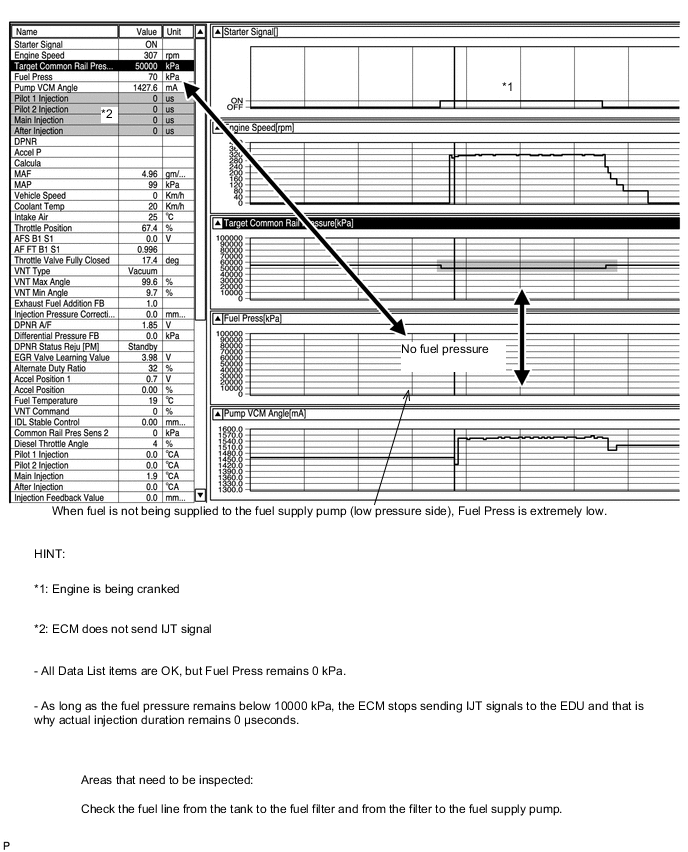
If there is a fault with the fuel supply pump (lack of discharge quantity) or pressure discharge valve (will not fully close), the fuel pressure will drop. Also, a blocked fuel filter, leakage from fuel pipes, and lack of fuel will also make the fuel pressure drop.
-
If air mixes with the fuel, the fuel pressure will shift away from the target fuel pressure.
-
When there is a fault with the fuel supply pump, there is a possibility of lack of power, engine stall, rough idle and difficulty starting.
-
Fuel press is the actual common rail fuel pressure.
-
Inspect by comparing Fuel Press with Target Common Rail Pressure.
-
The ECM uses Fuel Press for feedback control of Target Fuel Pressure via the supply pump.
The injection amount is determined based on the injection timing and fuel pressure.
Also, the spray pattern is selected based on the fuel pressure.
Results of real-vehicle check:
-
Ignition switch ON: 0 kPa
-
Cranking: 35390 kPa
-
Idling (warm up the engine): 33640 kPa (2 minutes after starting the vehicle)
-
Running without load (2500 rpm): 62920 kPa
-
Driving with the accelerator fully open at 2000 rpm: 134390 kPa
-
Driving with the accelerator fully open at 3000 rpm: 178670 kPa
Target Pump SCV Current Data List Judgment of Data List Values Faulty Component Diagnosis Note Target Pump SCV Current Idling after warming up: roughly 923 to 1123 mA. When this value is large, the pump is trying to increase the fuel discharge rate.
-
With this data, component fault not specified, use this data as a reference.
-
If the current is 3000 mA or more, there is a possibility the suction control valve is stuck.
-
ECU-calculated value for the suction control valve actuation target current.
-
Value is large when a high fuel pressure is desired.
-
When this deviates from the standard value, it indicates that for some reason, even though the pump is running hard, the actual fuel pressure is inconsistent with the target fuel pressure.
Results of real-vehicle check:
-
Ignition switch ON: 1008 mA
-
Cranking: 1155 mA
-
Running without load (2500 rpm): 1300 mA
-
Driving with the accelerator fully open at 2000 rpm: 1233 mA
-
Driving with the accelerator fully open at 3000 rpm: 1397 mA
Injection Feedback Val #1 (to #4) Data List Judgment of Data List Values Faulty Component Diagnosis Note Injection Feedback Val #1 (to #4)
-
When idling after the engine is warmed up, the fuel quantity of each fuel injector is corrected to make each cylinder engine speed equal.
-
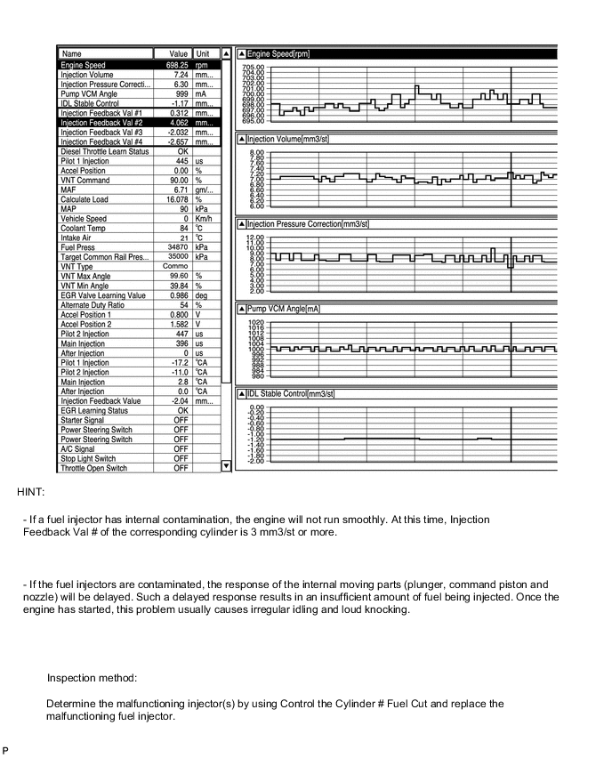
Cylinders more than 3 mm3/st may have a fault.
Tech Tips
Read the value after one minute of idling after warm up (engine coolant temperature above 70°C (158°F)). This value is only calculated when idling.
-
Fault with a fuel injector or lack of compression of a cylinder with a large Injection Feedback Val.
-
Do a compression Active Test. If there is a cylinder that is around 100 rpm more than the other cylinders, there is a possibility that the compression of that cylinder is being lost.
-
If all the cylinder speeds are even according to the compression Active Test result, the fuel injector of the cylinder may have a fault.
-
With fuel injector faults, other than difficulty starting, there is a possibility of rough idling, lack of power, black smoke, white smoke and knocking.
-
When idling after warm up, the injection amount for each cylinder is corrected to optimize the difference of each cylinder engine speed.
Example: For cylinders that are slowing the engine speed compared to other cylinders, the injection volume is increased.
-
"Injection Feedback Val" more than 3.0 mm3/st: Injector breakdown or insufficient compression is causing poor combustion.
Injection Volume Data List Judgment of Data List Values Faulty Component Diagnosis Note Injection Volume - - After warming up the engine, when Injection Volume during idling is 10 mm3/st or more, there is tendency for the injector to clog.
Results of real-vehicle check:
-
Cranking: 22 mm3/st (Note: Varies depending on coolant temperature)
-
Idling (warm up the engine): 5 mm3/st
-
Running without load (2500 rpm): 8 mm3/st
-
Running without load (4700 rpm): 16 mm3/st
-
Driving with the accelerator fully open at 2000 rpm: 75 mm3/st
-
Driving with the accelerator fully open at 3000 rpm: 78 mm3/st
-
-
Diesel Throttle
Actual Throttle Position Data List Judgment of Data List Values Faulty Component Diagnosis Note Actual Throttle Position
-
When the ignition switch is turned to ON (engine stopped), the diesel throttle is fully open. When the ignition switch is turned from ON to off, the diesel throttle is fully closed temporarily.
-
With the diesel throttle stuck almost fully closed, there is a possibility of rough idling, engine stall, black smoke, difficulty starting and lack of power.
Diesel throttle body Actual Throttle Position is the closing percentage of the throttle valve.
-
Fully closed: 100%
-
Fully open: 0%
Tech Tips
There is no connection with the accelerator. However, under full load, the throttle is usually fully open (0%).
Results of real-vehicle check:
-
Ignition switch ON: 0%
-
Cranking: -6%
-
Idling (warm up the engine): 93%
-
Running without load (2500 rpm): 51%
-
Driving with the accelerator fully open at 2000 rpm: 0%
-
Driving with the accelerator fully open at 3000 rpm: 0%
-
-
Diesel EGR
Target EGR Position Data List Judgment of Data List Values Faulty Component Diagnosis Note Target EGR Position - -
-
Fully open: 100%
-
Fully closed: 0%
-
Used for comparison to "Actual EGR Valve Pos".
Results of real-vehicle check:
-
Ignition switch ON: 0%
-
Cranking: 0%
-
Idling (warm up the engine): 54%
-
Running without load (2500 rpm): 47%
-
Driving with the accelerator fully open at 2000 rpm: 0%
-
Driving with the accelerator fully open at 3000 rpm: 0%
Actual EGR Valve Pos. Data List Judgment of Data List Values Faulty Component Diagnosis Note Actual EGR Valve Pos.
-
Generally Actual EGR Valve Pos. = Target EGR Pos. (Fully closed = 0%, Fully open = 100%)
-
The EGR valve Active Test can be used to check whether the Actual EGR Valve Pos. = Target EGR Pos.
EGR valve assembly
-
Inspect while comparing to "Target EGR Valve Pos.".
-
Sometimes the malfunction only occurs around a certain temperature, so refer to the engine coolant temperature and outside temperature at the time the malfunction occurred.
Results of real-vehicle check:
-
Ignition switch ON: 0%
-
Cranking: 0%
-
Idling (warm up the engine): 54%
-
Running without load (2500 rpm): 47%
-
Driving with the accelerator fully open at 2000 rpm: 0%
-
Driving with the accelerator fully open at 3000 rpm: 0%
EGR Close Lrn. Status Data List Judgment of Data List Values Faulty Component Diagnosis Note EGR Close Lrn. Status
-
"OK" means the fully closed position learning has completed normally.
-
When NG, the learned fully closed position may be outside of the normal range.
- After disconnecting and reconnecting the battery cable, if the ignition switch has not been turned off once, learning may not be completed. EGR Close Lrn. Val. Data List Judgment of Data List Values Faulty Component Diagnosis Note EGR Close Lrn. Val. When leaving the vehicle idling, with the EGR Close Lrn. Status OK, the normal range of EGR Close Lrn. Val. is within 0.34 to 0.70 V. In cases when EGR Close Lrn. Status is NG or EGR Close Lrn. Val. is at the maximum or minimum (0.34 to 0.70 V) of the normal range, it is possible that the EGR valve is not completely closed or a foreign object is lodged in the EGR valve seat area. -
-
This value is the EGR position sensor output voltage.
-
As the maximum and minimum settings are 0.34 V and 0.70 V, if the value becomes stuck at either of these, there is a malfunction in the lift sensor or the valve position is shifted (due to foreign matter, etc.).
-
-
-
Actual Examples of Malfunction
Tech Tips
-
The purpose of the following examples is help you to understand the relationship between each Data List item when a certain malfunction occurs. Understanding this relationship helps you to find the real root cause easier.
-
The following are examples of actual malfunctions of a common rail diesel engine.
-
Use them for reference when diagnosing malfunctions.
-
These are not data of the AVENSIS 2AD-FTV.
-
Fuel is not being supplied to supply pump (Low pressure fuel line clogged)
-
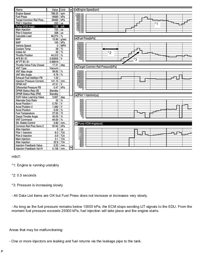
Fuel is not being injected (Injectors are leaking)
-
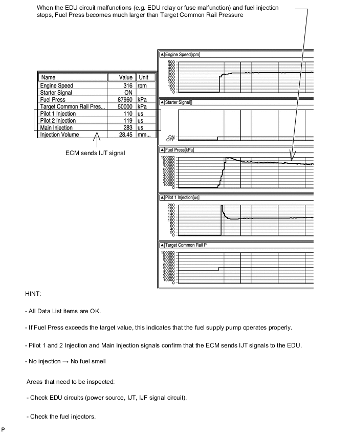
Fuel is not being injected (EDU circuit malfunction)
-
Fuel supply pump malfunction (Suction control valve momentarily sticking)

-
Increased opening delay of injectors (Internal contamination)
-
CAUTION / NOTICE / HINT
-
Explanation of Symptom
Starting Trouble For good starting it is essential to have:
-
Sufficient cranking speed.
-
Properly operating engine preheating system.
-
Good quality fuel.
The fuel is ignited by the heat which is generated with compression pressure.
With problems such as a depleted battery, the crankshaft speed can become low, or if the engine compression is leaking, the compression pressure will not rise and there will be difficulty starting.
When the engine is cold, even if there is compression heat, it will escape from the combustion chamber. For this reason, when the engine is started when it is cold, the glow plugs heat the compressed air.
Also, after starting the engine, by charging the glow plugs for a fixed time set according to the engine coolant temperature, diesel knocking and white smoke are prevented. The quantity of fuel injected is determined by the fuel pressure and also the amount of time the fuel injector is open.
-
-
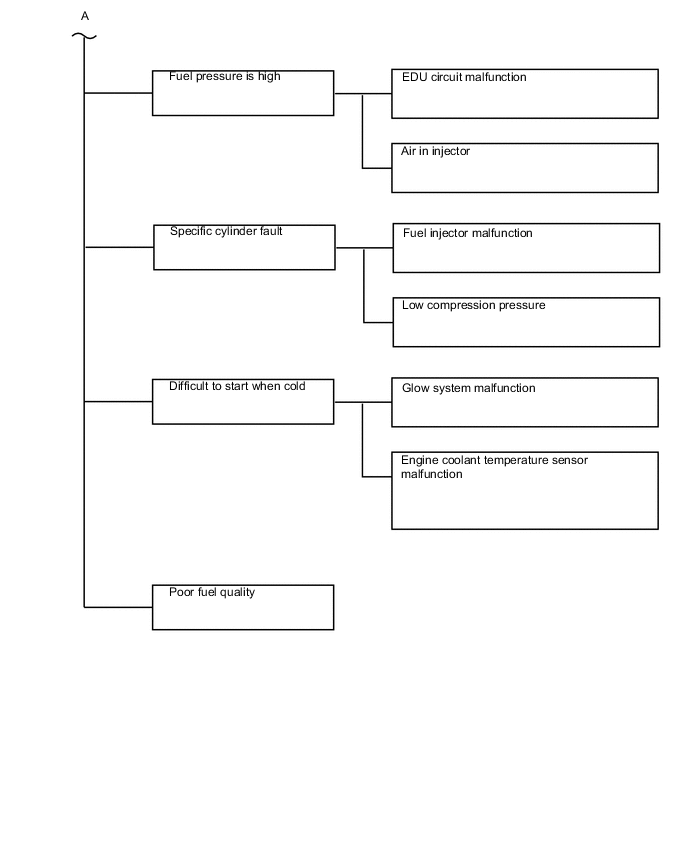
Trouble Area Chart According to Problem Cause
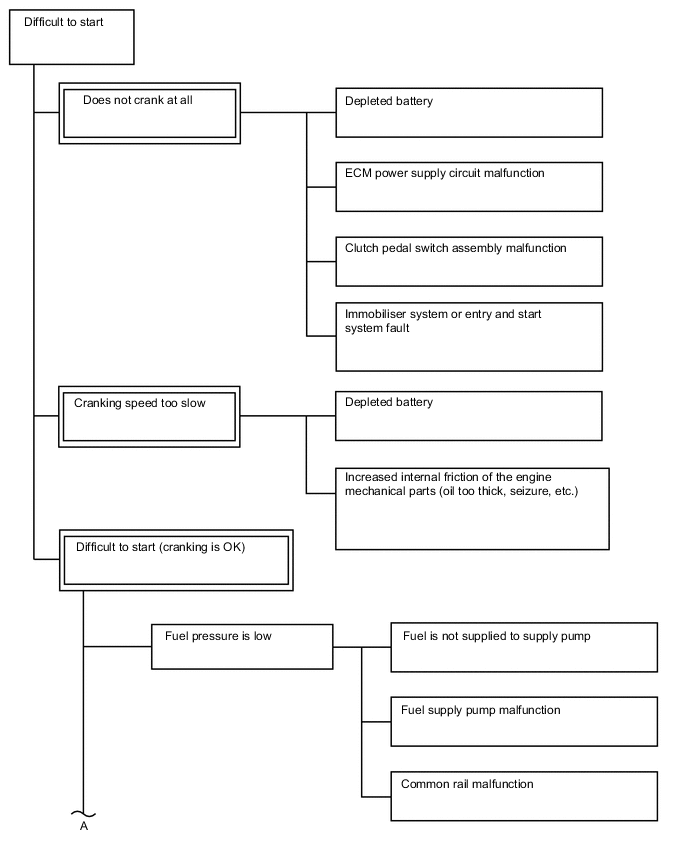
Note
-
After replacing the ECM, the new ECM needs registration (See page ) and initialization Click here.
-
After replacing the fuel supply pump, the ECM needs initialization Click here.
-
After replacing a fuel injector, the ECM needs registration Click here.
Tech Tips
-
Specified values in the following troubleshooting flowchart are for reference only. Variations in the Data List values may occur depending on the measuring conditions or the vehicle age. Do not assume the vehicle is normal when the Data List outputs standard values. There may be concealed factors of the malfunction.
-
PROCEDURE
-
CHECK ENGINE CRANKING CONDITION
-
Check the engine cranking condition.
Result Result Proceed to Does not crank at all. A Low cranking speed.
Tech Tips
When cranking speed is low, especially when the temperature is low, check if the engine oil grade matches the recommendation.
B Cranking is OK. C
B 
CHECK BATTERY CONDITION Click here
C 
CHECK FUEL RECEIVER GAUGE (AMOUNT OF FUEL) Click here
A 
-
-
CHECK BATTERY CONDITION
-
Check the battery condition Click here.
NG
REPLACE BATTERY
OK
-
-
CHECK COMMUNICATION BETWEEN INTELLIGENT TESTER AND ECM
-
Connect the intelligent tester to the DLC3.
-
Turn the ignition switch to ON and turn the tester on.
-
Check if the normal starting screen appears (check whether communication with the ECM is possible).
Tech Tips
Use a tester that is able to communicate with other vehicles.
OK Communication is possible (vehicle can be recognized).
NG
GO TO ECM POWER SOURCE CIRCUIT Click here
OK
-
-
READ VALUE USING INTELLIGENT TESTER (CLUTCH SWITCH)
-
Connect the intelligent tester to the DLC3.
-
Turn the ignition switch to ON and turn the tester on.
-
Enter the following menus: Powertrain / Engine and ECT / Data List / All Data / Clutch Switch.
-
Read the value displayed on the tester.
Standard Value Tester Display Condition Specified Condition Clutch Switch Clutch pedal depressed ON Result Result Proceed to OK A NG B
B
REPLACE CLUTCH START SWITCH Click here
A
-
-
READ ALL OUTPUT DTCS
-
Connect the intelligent tester to the DLC3.
-
Turn the ignition switch to ON and turn the tester on.
-
Enter the following menus: Utility / All Codes.
Result Result Proceed to No DTC is output A DTCs related to engine are output B
B
GO TO RELATED DTC
A
-
-
INSPECT ENTRY AND START SYSTEM (FOR ENTRY AND START SYSTEM)
-
Check if the "Door Control Transmitter" function of each key functions properly.
Tech Tips
-
Check if the engine starts properly with another key.
-
If the doors cannot be opened/closed by using the "Door Control Transmitter" function of the key, the battery inside the key may be depleted. In such a case, the engine cannot be started by pushing the engine switch.
-
When the door control transmitter battery is depleted, the engine can only be started by holding the door control transmitter against the engine switch.
-
If the inspection result is that the problem only occurs in certain locations or times of day, the possibility of wave interference is high. Also, added vehicle components may cause wave interference. If any optional components are installed, remove them and perform the operation check.
Near broadcasting stations, large screens, airports, transformer stations, gasoline stations, etc., the door control transmitter may not operate due to electric wave interference.
-
NEXT
-
-
INSPECT STARTER SIGNAL CIRCUIT
Tech Tips
Check that "Starter Signal" in the Data List changes to ON when the engine is started.
-
Inspect the starter signal circuit Click here.
NEXT
END
-
-
CHECK FUEL RECEIVER GAUGE (AMOUNT OF FUEL)
-
Check if the fuel level is low.
Result Result Proceed to The indicator (fuel warning light) is not illuminated A The indicator (fuel warning light) is illuminated B
B
ADD FUEL Click here
A
-
-
CHECK INITIALIZATION (FUEL SUPPLY PUMP)
-
When the engine does not start or another problem such as rough idling is present, perform initialization and check to see if the problem symptoms disappear. If the problem symptoms do not disappear, perform the next procedure.
Tech Tips
When replacing the ECM, the supply pump initialization must be performed Click here.
NEXT
-
-
READ OUTPUT DTC (RELATED TO ENGINE)
-
Connect the intelligent tester to the DLC3.
-
Turn the ignition switch to ON and turn the tester on.
-
Enter the following menus: Powertrain / Engine and ECT / DTC.
-
Read the DTCs.
Result Result Proceed to No DTC is output A DTCs related to engine are output B
B
REPAIR OR REPLACE ENGINE CONTROL SYSTEM ACCORDING TO DTC OUTPUT Click here
A
-
-
TAKE SNAPSHOT DURING STARTING AND IDLING
-
Connect the intelligent tester to the DLC3.
-
Turn the ignition switch to ON and turn the tester on.
-
Enter the following menus: Powertrain / Engine and ECT / Data List / All Data.
-
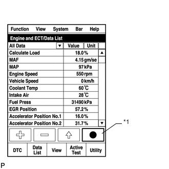
*1 Snapshot Button Take a snapshot of the following Data List items with the intelligent tester during "ignition switch ON (5 seconds) → Starting → Idling (10 seconds)".
Tech Tips
-
A snapshot can be used to compare vehicle data from the time of the malfunction to normal data and is very useful for troubleshooting. The data in the illustration below is that of a normal vehicle, but as the data varies between individual vehicles, this data should only be used for reference.
-
When there is trouble starting with a cold engine, take the snapshot when the engine is cold. Then warm up the engine (engine coolant temperature 70°C (158°F) or more) and after idling the vehicle for 1 minute (A/C off, electrical load off), take a snapshot of the data for 15 seconds while idling.
-
Graphs like the ones shown below can be displayed by transferring the stored snapshot from the tester to a PC. Intelligent Viewer must be installed on the PC.
Data List Starter Signal Engine Speed Fuel Press Target Common Rail Pressure Target Pump SCV Current Injection Volume Main Injection Period Inj. FB Vol. for Idle Injection Feedback Val #1 Injection Feedback Val #2 Injection Feedback Val #3 Injection Feedback Val #4 Battery Voltage Actual EGR Valve Pos. Target EGR Position Actual Throttle Position MAF Target Booster Pressure MAP 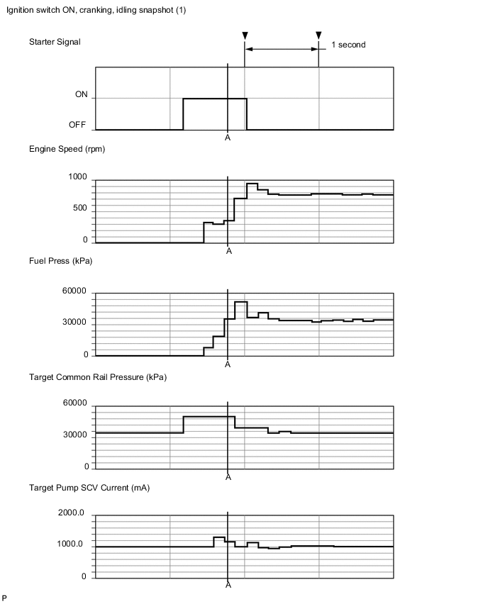
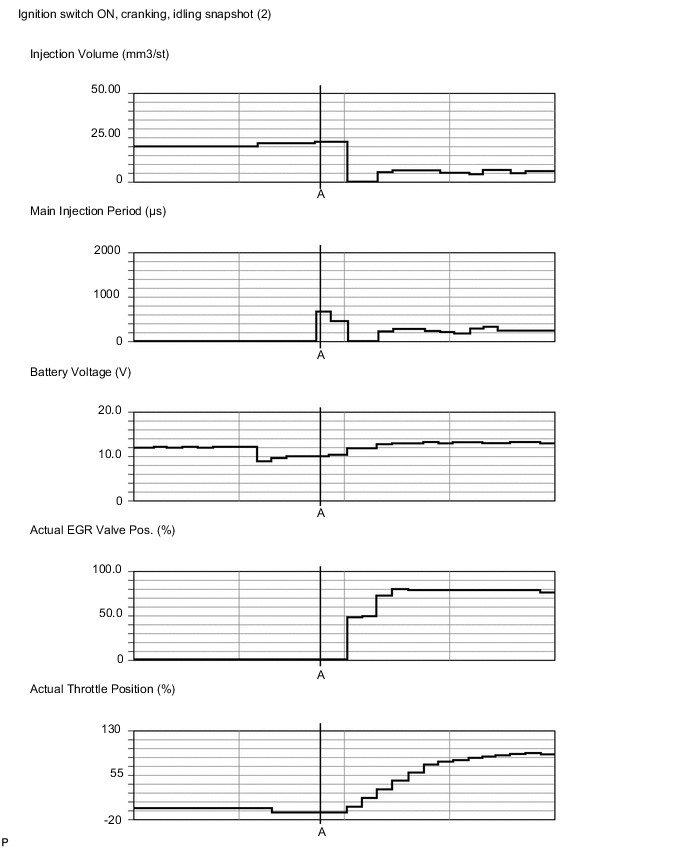
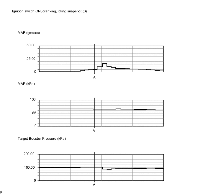
Reference Values during Engine Start (Point A) Data List Value Unit Starter Signal ON - Engine Speed 366 rpm Fuel Press 35390 kPa Target Common Rail Pressure 50000 kPa Injection Volume 22.57 mm3/st
Main Injection Period 682 μs Inj. FB Vol. for Idle 0.70 mm3/st
Battery Voltage 10.1 V Target EGR Position 0 % Actual EGR Valve Pos. 0 % Actual Throttle Position -6 % MAF 5.07 g/sec MAP 99 kPa Target Boost Pressure 101.34 kPa Coolant Temp 75 °C Data Condition at Idling (Engine Warmed Up) Data List Value Unit Engine Speed 771 rpm Target Booster Pressure 92.69 kPa MAP 94 kPa MAF 3.87 g/sec Target Common Rail Pressure 35000 kPa Fuel Press 33640 kPa Injection Volume 5.15 mm3/st
Actual EGR Valve Pos. 54.1 % Actual Throttle Position 93 % Injection Feedback Val #1 0.0 mm3/st
Injection Feedback Val #2 -0.5 mm3/st
Injection Feedback Val #3 0.0 mm3/st
Injection Feedback Val #4 0.1 mm3/st
Target EGR Position 54.1 % Coolant Temp 76 °C Tech Tips
Actual Examples of Malfunction (See "Diagnostic Help" menu)
-
Starting is not possible
-
Fuel is not supplied to supply pump.
Fuel Press: Approximately 1000 kPa or less during cranking.
-
Fuel is not being injected due to EDU circuit malfunction.
Fuel Press: 80000 to 90000 kPa during cranking.
-
Air in injectors.
Fuel Press: 60000 to 70000 kPa during cranking.
-
Cranking time is long
-
Suction control valve is stuck.
Target Pump SCV Current intermittently reaches 3000 mA or more. The suction control valve plunger intermittently becomes stuck. If there is difficulty starting when the engine is cold, cool the engine and inspect it.
-
Injector clogging or internal contamination:
Injection Feedback Val # of one or more of the cylinders is 3 mm3/st or more.
Injection Feedback Val # can be read when the engine is idling after being warmed up.
-
NEXT
-
-
CHECK SNAPSHOT (FUEL PRESS)
-
Check Fuel Press in the snapshot taken when the engine was starting.
Result Result Proceed to 2 seconds after Starter Signal turns from OFF to ON, Fuel Press is less than 25000 kPa
Tech Tips
As long as the fuel pressure remains below 5000 kPa, the ECM stops sending the injection open signal (IJT) to the EDU, and then the actual injection duration remains 0 microseconds.
A 2 seconds after Starter Signal turns from OFF to ON, Fuel Press is 50000 kPa or more B Except above C Tech Tips
-
Fuel pressure is about 20000 to 35000 kPa when the engine is cranking and the engine coolant temperature is 0°C (32°F) or more.
-
Fuel pressure increases rapidly during cranking.
-
B
CHECK SNAPSHOT Click here
C
CHECK SNAPSHOT (TARGET PUMP SCV CURRENT) Click here
A
-
-
READ VALUE USING INTELLIGENT TESTER (FUEL PRESS)
-
Using the hand pump mounted on the fuel filter cap, bleed the air from the fuel system. Continue pumping until the pump resistance increases.*1
Note
-
Hand pump pumping speed: Maximum of 2 strokes/second.
-
Be sure to push the hand pump with a full stroke during pumping.
-
When the fuel pressure at the supply pump inlet port reaches a saturated pressure, the hand pump resistance increases.
-
If pumping is interrupted during the air bleeding process, fuel in the fuel line may return to the fuel tank. Continue pumping until the hand pump resistance increases.
-
If the hand pump resistance does not increase despite consecutively pumping 200 times or more, there may be a fuel leak between the fuel tank and fuel filter, the hand pump may be malfunctioning, or the vehicle may have run out of fuel.
-
If air bleeding using the hand pump is incomplete, the common rail pressure does not rise to the pressure range necessary for normal use, and the engine cannot be started.
-
-
Start the engine.
Note
-
Just after starting the engine, visually check for fuel leaks from the supply pump, fuel injector, common rail, and the fuel pipes in high-pressure areas.
-
Even if air bleeding using the hand pump has been completed, the starter may need to be cranked for 10 seconds or more to start the engine.
-
Do not crank the engine continuously for more than 20 seconds. The battery may be discharged.
-
Use a fully-charged battery.
-
When the engine can be started, proceed to step *2.
-
If the engine cannot be started, bleed the air again using the hand pump until the hand pump resistance increases (refer to step *1). Then start the engine.
-
-
Turn the ignition switch off.*2
-
Connect the intelligent tester to the DLC3.
-
Turn the ignition switch to ON and turn the tester on.
-
Clear DTCs Click here.
-
Start the engine.*3
-
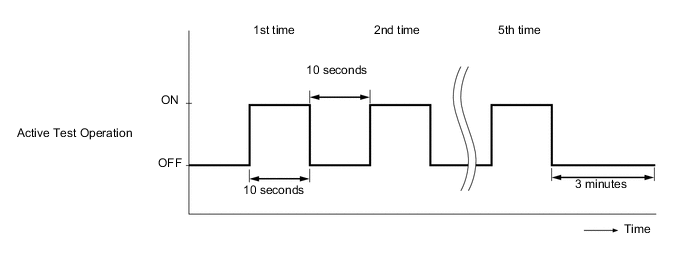
Enter the following menus: Powertrain / Engine and ECT / Active Test / Test the Fuel Leak.*4
-
Perform the following test 5 times with on/off intervals of 10 seconds: Active Test / Test the Fuel Leak.*5
-
Allow the engine to idle for 3 minutes or more after performing the Active Test for the fifth time.*6
-
Enter the following menus: Powertrain / Engine and ECT / DTC.
-
Read Current DTCs.
-
When no DTCs are output, the air bleeding is completed. Proceed to step *8.
-
If any DTCs are output, proceed to step *7.
-
-
Clear DTCs Click here.*7
-
Repeat steps *3 to*6.
-
Enter the following menus: Powertrain / Engine and ECT / Data List / Fuel Press.*8
-
Start the engine.
-
Read the Fuel Press values while cranking and idling the engine.
Result Result Proceed to The engine cannot be started or the engine can be started but Fuel Press is less than 25000 kPa 2 seconds after the starter signal changes from OFF to ON. B Except above A
A
END
B
CHECK IF FUEL IS BEING SUPPLIED TO FUEL SUPPLY PUMP Click here
-
-
CHECK SNAPSHOT (TARGET PUMP SCV CURRENT)
-
Check Target Pump SCV Current in the snapshot taken when the engine was starting.
Result Result Proceed to Target Pump SCV Current is 3000 mA or more A Target Pump SCV Current is less than 3000 mA B
A
CHECK HARNESS AND CONNECTOR (SUCTION CONTROL VALVE - ECM) Click here
B
-
-
CHECK ENGINE STARTING CONDITION
-
Check whether the engine can be started.
Tech Tips
If there are deposits in the injectors and they are left for a long time, the injectors for all the cylinders may become stuck.
Result Result Proceed to The engine can be started. A There is no initial combustion even when the engine can be cranked. B
B
REPLACE FUEL INJECTORS OF ALL CYLINDERS Click here
A
-
-
CHECK DATA LIST
-
*1 Snapshot Button Check Injection Feedback Val # and Injection Volume in the snapshot taken when the engine was idling.
Result Result Proceed to Injection Feedback Val #1 to #4 is outside the range of +/-3 mm3/st
Tech Tips
There may be a malfunction in the corresponding cylinder.
A Injection Feedback Val #1 to #4 is within the range of +/-3 mm3/st and Injection Volume is more than 10 mm3/st
B* Injection Feedback Val #1 to #4 is within the range +/-3 mm3/st and Injection Volume is 10 mm3/st or less
C Tech Tips
*: When case "B" occurs, usually symptoms may be noticeable, such as difficult starting, rough idling, knocking or black smoke at high common rail pressure.
B
REPLACE FUEL INJECTORS OF ALL CYLINDERS Click here
C
CHECK TEMPERATURE WHEN STARTING TROUBLE OCCURS Click here
A
-
-
PERFORM ACTIVE TEST USING INTELLIGENT TESTER (CONTROL THE CYLINDER #1 TO #4 FUEL CUT)
Tech Tips
Use this Active Test to determine the malfunctioning cylinder.
-
Connect the intelligent tester to the DLC3.
-
Start the engine and turn the tester on.
-
Enter the following menus: Powertrain / Engine and ECT / Active Test / Control the Cylinder #1 to #4 Fuel Cut.
Tech Tips
-
If the engine idle speed does not change when a fuel injector is disabled, the cylinder being tested is malfunctioning.
-
If the cylinder being tested is normal, there will be a significant change in idle speed when the fuel injection is stopped for that cylinder.
-
NEXT
-
-
PERFORM ACTIVE TEST USING INTELLIGENT TESTER (CHECK THE CYLINDER COMPRESSION)
Tech Tips
Use this Active Test to help determine whether a cylinder has compression loss or not.
-
Connect the intelligent tester to the DLC3.
-
Turn the ignition switch to ON and turn the tester on.
-
Enter the following menus: Powertrain / Engine and ECT / Active Test / Check the Cylinder Compression / Data List / Compression / Engine Speed of Cyl #1 to #4.
-
Check the engine speed during the Active Test.
OK The values of Engine Speed Cyl #1 to #4 are within +/-10 rpm of each other. Tech Tips
When cranking, if the speed of a cylinder is approximately 100 rpm more than the other cylinders, there is probably a loss of compression in that cylinder.
OK
REPLACE FUEL INJECTOR OF MALFUNCTIONING CYLINDER Click here
NG
-
-
CHECK CYLINDER COMPRESSION PRESSURE OF MALFUNCTIONING CYLINDER
Tech Tips
Measure the compression of the cylinder that had a high speed during the Active Test "Check the Cylinder Compression".
-
Check the cylinder compression pressure Click here.
NG
CHECK ENGINE TO DETERMINE CAUSE OF LOW COMPRESSION
OK
-
-
REPLACE FUEL INJECTOR OF MALFUNCTIONING CYLINDER
Tech Tips
The injector is determined to be faulty as the corresponding cylinder is malfunctioning, but has no compression loss.
-
Replace the fuel injector Click here.
NEXT
BLEED AIR FROM FUEL SYSTEM Click here
-
-
CHECK TEMPERATURE WHEN STARTING TROUBLE OCCURS
-
Check the temperature when starting trouble occurs.
Result Result Proceed to Difficult to start only for cold engine. A Difficult to start both for cold and warmed up engine. B
B
CHECK FUEL QUALITY Click here
A
-
-
INSPECT ENGINE COOLANT TEMPERATURE SENSOR
-
Inspect the engine coolant temperature sensor Click here.
NG
REPLACE ENGINE COOLANT TEMPERATURE SENSOR Click here
OK
-
-
INSPECT GLOW PLUG ASSEMBLY (RESISTANCE)
-
Disconnect the glow plug wire.
-
Measure the resistance according to the value(s) in the table below.
Standard Resistance Tester Connection Condition Specified Condition Glow plug terminal - Body ground 20°C (68°F) Approximately 1.0 Ω Tech Tips
If any of the glow plugs has an open circuit, the engine power will be insufficient only when the engine is cold.
Note
-
Exercise extreme care not to damage the glow plug pipes. Damaging them could cause an open circuit or shorten the life of the glow plugs.
-
Keep the glow plugs free of oil and fuel while cleaning.
-
Wipe any oil off of the terminal and Bakelite washer with a clean, dry cloth during inspection.
-
Do not apply more than 11 V to the glow plugs as it may cause an open circuit.
-
NG
REPLACE GLOW PLUG ASSEMBLY Click here
OK
-
-
INSPECT INJECTOR COMPENSATION CODE
-
Read the injector compensation code Click here.
OK Compensation codes stored in the ECM match compensation codes of the installed fuel injectors.
NG
REGISTER FUEL INJECTOR COMPENSATION CODE Click here
OK
-
-
CHECK FUEL QUALITY
-
Check that fuel with a low cetane number is used.
NEXT
-
-
CONFIRM WHETHER MALFUNCTION HAS BEEN SUCCESSFULLY REPAIRED
-
Check whether the difficulty starting has been successfully repaired by starting the engine.
NEXT
END
-
-
CHECK SNAPSHOT
Tech Tips
When all Data List values are OK and Fuel Press is higher than Target Common Rail Pressure, perform the following inspection.
NEXT
-
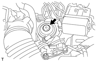
INSPECT INJECTOR DRIVER (EDU POWER SOURCE)
-
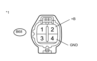
Text in Illustration *1 Front view of wire harness connector
(to Injector Driver (EDU))
Disconnect the injector driver (EDU) connectors.
-
Measure the voltage according to the value(s) in the table below.
Standard Voltage Tester Connection Switch Condition Specified Condition B68-2 (+B) - B68-4 (GND) Ignition switch ON 11 to 14 V -
Reconnect the injector driver (EDU) connectors.
NG
GO TO INJECTOR CIRCUIT Click here
OK
-
-
INSPECT FUEL INJECTOR
Tech Tips
If there is no initial combustion during cranking, there may be air in the injectors.
NEXT
END
-
CHECK HARNESS AND CONNECTOR (SUCTION CONTROL VALVE - ECM)
-
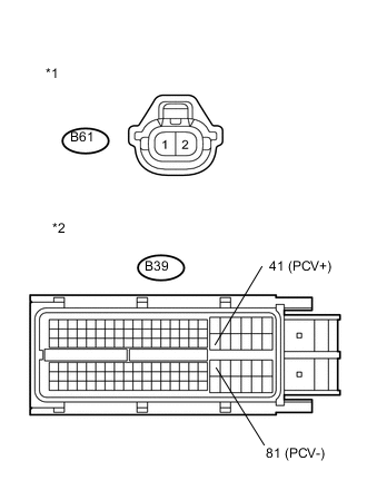
Text in Illustration *1 Front view of wire harness connector
(to Suction Control Valve)
*2 Front view of wire harness connector
(to ECM)
Disconnect the suction control valve connector.
-
Disconnect the ECM connector.
-
Measure the resistance according to the value(s) in the table below.
Standard Resistance (Check for Open) Tester Connection Condition Specified Condition B61-1 (+B) - B39-41 (PCV+) Always Below 1 Ω B61-2 (PCV) - B39-81 (PCV-) Always Below 1 Ω Standard Resistance (Check for Short) Tester Connection Condition Specified Condition B61-1 (+B) or B39-41 (PCV+) - Body ground Always 10 kΩ or higher B61-2 (PCV) or B39-81 (PCV-) - Body ground Always 10 kΩ or higher -
Reconnect the suction control valve connector.
-
Reconnect the ECM connector.
NG
REPAIR OR REPLACE HARNESS OR CONNECTOR
OK
-
-
CHECK IF FUEL IS BEING SUPPLIED TO FUEL SUPPLY PUMP
-
Disconnect the inlet hose from the fuel supply pump.
-
Operate the priming pump and check that fuel is being supplied to the fuel supply pump.
OK Fuel is properly supplied to the fuel supply pump when the priming pump is operated. Tech Tips
-
When there is a lack of fuel, fuel pressure drops.
-
Inspect for fuel filter clogging (check that the fuel filter is not clogged).
-
OK
REPLACE SUCTION CONTROL VALVE Click here
NG
CHECK AND REPLACE CLOGGED FUEL PIPE (INCLUDING FUEL FREEZING) (FUEL TANK - FUEL SUPPLY PUMP) Click here
-
-
CHECK IF FUEL IS BEING SUPPLIED TO FUEL SUPPLY PUMP
-
Disconnect the inlet hose from the fuel supply pump.
-
Operate the priming pump and check that fuel is being supplied to the fuel supply pump.
OK Fuel is properly supplied to the fuel supply pump when the priming pump is operated. Tech Tips
-
When there is lack of fuel, fuel pressure drops.
-
Inspect for fuel filter clogging.
(Check that the fuel filter is not clogged)
-
NG
CHECK AND REPLACE CLOGGED FUEL PIPE (INCLUDING FUEL FREEZING) (FUEL TANK - FUEL SUPPLY PUMP) Click here
OK
-
-
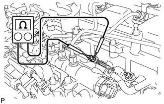
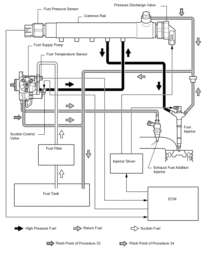
CHECK FOR FUEL LEAK (PROCEDURE 33) (FUEL SUPPLY PUMP)
-
Connect the intelligent tester to the DLC3.
-
Turn the ignition switch to ON and turn the tester on.
-
Enter the following menus: Powertrain / Engine and ECT / Data List / Fuel Press.
-
Pinch the supply pump return hose and check that Fuel Press increases during cranking.
Result Result Proceed to Fuel Press increases A No change B
A
REPLACE SUCTION CONTROL VALVE Click here
B
-
-
CHECK FOR FUEL LEAK (PROCEDURE 34) (PRESSURE DISCHARGE VALVE (COMMON RAIL))
-
Connect the intelligent tester to the DLC3.
-
Turn the ignition switch to ON and turn the tester on.
-
Enter the following menus: Powertrain / Engine and ECT / Data List / Fuel Press.
-
Pinch the pressure discharge valve return hose and check that Fuel Press increases during cranking.
Result Result Proceed to Fuel Press increases A No change B
A
REPLACE COMMON RAIL Click here
B
-
-
INSPECT FUEL INJECTOR (INSPECTION FOR VALVE CLOSING PROBLEM)
-
Remove the glow plug assembly for all the cylinders Click here.
-
Visually check if there is fuel on the glow plugs.
Tech Tips
-
If there is fuel on a glow plug, fuel may be leaking from a fuel injector.
-
After replacing a fuel injector, make sure that the common rail pressure (fuel pressure) is within +/-5000 kPa of the target fuel pressure while cranking the engine.
-
If there is fuel on a glow plug, fuel may have mixed with the engine oil. Check the engine oil amount and whether the engine oil smells of diesel fuel. If the oil level is above the full line or the engine oil smells of diesel fuel, replace the engine oil.
Result Result Proceed to No fuel on glow plugs A Fuel on glow plugs B -
-
Install the glow plug assembly Click here.
B
REPLACE FUEL INJECTOR (FUEL INJECTOR OF MALFUNCTIONING CYLINDER) Click here
A
-
-
REPLACE SUCTION CONTROL VALVE
-
Replace the suction control valve Click here.
NEXT
-
-
BLEED AIR FROM FUEL SYSTEM
-
Bleed the air from the fuel system Click here.
NEXT
-
-
PERFORM FUEL SUPPLY PUMP INITIALIZATION
-
Perform fuel supply pump initialization Click here.
NEXT
-
-
READ VALUE USING INTELLIGENT TESTER (FUEL PRESS)
-
Connect the intelligent tester to the DLC3.
-
Turn the ignition switch to ON and turn the tester on.
-
Enter the following menus: Powertrain / Engine and ECT / Data List / Fuel Press.
-
Start the engine.
-
Read the Fuel Press values while cranking and idling the engine.
Result Result Proceed to The engine cannot be started or the engine can be started but Fuel Press is less than 25000 kPa 2 seconds after the starter signal changes from OFF to ON. B Except above A
A
END
B
-
-
REPLACE COMMON RAIL
-
Replace the common rail Click here.
NEXT
-
-
BLEED AIR FROM FUEL SYSTEM
-
Bleed the air from the fuel system Click here.
NEXT
-
-
CONFIRM WHETHER MALFUNCTION HAS BEEN SUCCESSFULLY REPAIRED
-
Check whether the difficulty starting has been successfully repaired by starting the engine.
NEXT
END
-
-
REPLACE FUEL INJECTOR (FUEL INJECTOR OF MALFUNCTIONING CYLINDER)
-
Replace the fuel injector Click here.
NEXT
BLEED AIR FROM FUEL SYSTEM Click here
-
-
REPLACE FUEL INJECTORS OF ALL CYLINDERS
-
Replace the fuel injectors Click here.
NEXT
-
-
BLEED AIR FROM FUEL SYSTEM
-
Bleed the air from the fuel system Click here.
NEXT
-
-
REGISTER INJECTOR COMPENSATION CODE AND PERFORM PILOT QUANTITY LEARNING
-
Register the injector compensation codes Click here.
-
Perform the fuel injector pilot quantity learning Click here.
NEXT
-
-
CONFIRM WHETHER MALFUNCTION HAS BEEN SUCCESSFULLY REPAIRED
-
Check whether the difficulty starting has been successfully repaired by starting the engine.
NEXT
END
-
-
CHECK AND REPLACE CLOGGED FUEL PIPE (INCLUDING FUEL FREEZING) (FUEL TANK - FUEL SUPPLY PUMP)
-
Check and replace the clogged fuel pipe.
NEXT
BLEED AIR FROM FUEL SYSTEM Click here
-
-
ADD FUEL
-
Add fuel.
NEXT
-
-
BLEED AIR FROM FUEL SYSTEM
-
Bleed the air from the fuel system Click here.
NEXT
-
-
CONFIRM WHETHER MALFUNCTION HAS BEEN SUCCESSFULLY REPAIRED
-
Check whether the difficulty starting has been successfully repaired by starting the engine.
NEXT
END
-