ECD SYSTEM Starter Signal Circuit
DESCRIPTION
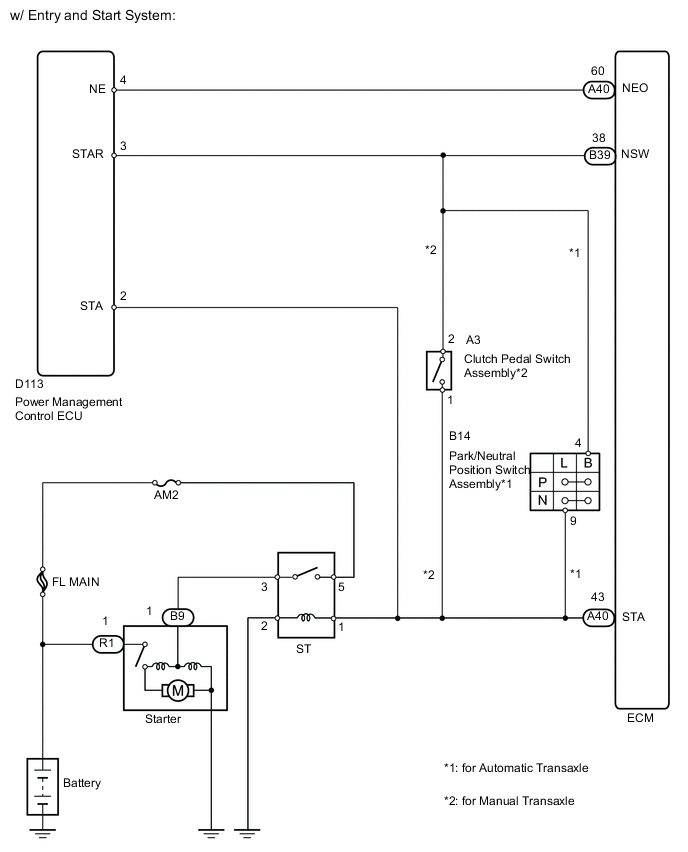
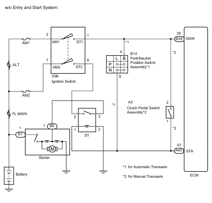
While the engine is being cranked, current flows from terminal ST2 of the ignition switch to the ST fuse and also flows to terminal STA of the ECM (STA signal).
WIRING DIAGRAM
CAUTION / NOTICE / HINT
Note
-
Inspect the fuses of circuits related to this system before performing the following inspection procedure.
-
After replacing the ECM, the new ECM needs registration (See page ) and initialization Click here.
Tech Tips
This chart is based on the premise that the engine can crank normally. If the engine cannot crank normally, proceed to the problem symptoms table Click here.
PROCEDURE
-
CHECK IF VEHICLE IS EQUIPPED WITH ENTRY AND START SYSTEM
-
Check if the vehicle is equipped with the entry and start system.
Result Result Proceed to w/o Entry and Start System A w/ Entry and Start System B
B 
READ VALUE USING INTELLIGENT TESTER (STARTER SIGNAL) Click here
A 
-
-
READ VALUE USING INTELLIGENT TESTER (STARTER SIGNAL)
-
Connect the intelligent tester to the DLC3.
-
Turn the ignition switch to ON.
-
Turn the tester on.
-
Enter the following menus: Powertrain / Engine and ECT / Data List / Starter Signal.
-
Read the value.
OK Ignition Switch Position Starter Signal ON OFF START ON
OK 
PROCEED TO NEXT SUSPECTED AREA SHOWN IN PROBLEM SYMPTOMS TABLE Click here
NG
-
-
CHECK STARTER RELAY (POWER SOURCE)
-
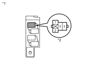
Text in Illustration *1 No. 1 Relay Block *2 ST Relay Remove the ST relay from the No. 1 relay block.
-
Measure the voltage according to the value(s) in the table below.
Standard Voltage Tester Connection Condition Specified Condition ST relay terminal 1 - Body ground Engine cranking 11 to 14 V Result Result Proceed to OK A NG (for Manual transaxle) B NG (for Automatic transaxle) C Tech Tips
The engine does not crank because the relay is not installed.
-
Reinstall the ST relay.
B
CHECK HARNESS AND CONNECTOR (ST RELAY - CLUTCH PEDAL SWITCH ASSEMBLY) Click here
C
CHECK HARNESS AND CONNECTOR (ST RELAY - PARK/NEUTRAL POSITION SWITCH) Click here
A
-
-
INSPECT STARTER RELAY
-
Remove the ST relay from the No. 1 relay block.
-
Measure the resistance according to the value(s) in the table below.
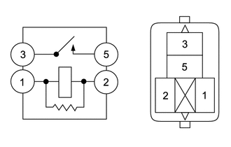
Standard Resistance Tester Connection Condition Specified Condition 3 - 5 Battery voltage not applied between terminals 1 and 2 10 kΩ or higher 3 - 5 Battery voltage applied between terminals 1 and 2 Below 1 Ω -
Reinstall the ST relay.
NG
REPLACE STARTER RELAY
OK
-
-
CHECK HARNESS AND CONNECTOR (ST RELAY - BODY GROUND)
-
Text in Illustration *1 No. 1 Relay Block *2 ST Relay Remove the ST relay from the No. 1 relay block.
-
Measure the resistance according to the value(s) in the table below.
Standard Resistance Tester Connection Condition Specified Condition ST relay terminal 2 - Body ground Always Below 1 Ω -
Reinstall the ST relay.
OK
REPAIR OR REPLACE HARNESS OR CONNECTOR (ECM - CLUTCH PEDAL SWITCH ASSEMBLY OR PARK/NEUTRAL POSITION SWITCH ASSEMBLY)
NG
REPAIR OR REPLACE HARNESS OR CONNECTOR (ST RELAY - BODY GROUND)
-
-
CHECK HARNESS AND CONNECTOR (ST RELAY - CLUTCH PEDAL SWITCH ASSEMBLY)
-
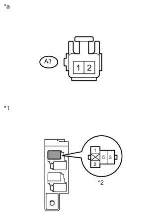
Text in Illustration *1 No. 1 Relay Block *2 ST Relay *a Front view of wire harness connector
(to Clutch Pedal Switch Assembly)
Remove the ST relay from the No. 1 relay block.
-
Disconnect the clutch pedal switch assembly connector.
-
Measure the resistance according to the value(s) in the table below.
Standard Resistance (Check for Open) Tester Connection Condition Specified Condition ST relay terminal 1 - A3-1 Always Below 1 Ω Standard Resistance (Check for Short) Tester Connection Condition Specified Condition ST relay terminal 1 or A3-1 - Body ground Always 10 kΩ or higher -
Reinstall the ST relay.
-
Reconnect the clutch pedal switch assembly connector.
NG
REPAIR OR REPLACE HARNESS OR CONNECTOR (ST RELAY - CLUTCH PEDAL SWITCH ASSEMBLY)
OK
-
-
CHECK HARNESS AND CONNECTOR (CLUTCH PEDAL SWITCH ASSEMBLY - IGNITION SWITCH ASSEMBLY)
-
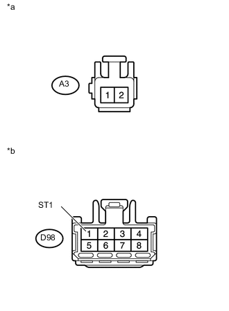
Text in Illustration *a Front view of wire harness connector
(to Clutch Pedal Switch Assembly)
*b Front view of wire harness connector
(to Ignition Switch Assembly)
Disconnect the clutch pedal switch assembly connector.
-
Disconnect the ignition switch assembly connector.
-
Measure the resistance according to the value(s) in the table below.
Standard Resistance (Check for Open) Tester Connection Condition Specified Condition A3-2 - D98-1 (ST1) Always Below 1 Ω Standard Resistance (Check for Short) Tester Connection Condition Specified Condition A3-2 or D98-1 (ST1) - Body ground Always 10 kΩ or higher -
Reconnect the clutch pedal switch assembly connector.
-
Reconnect the ignition switch assembly connector.
NG
REPAIR OR REPLACE HARNESS OR CONNECTOR (CLUTCH PEDAL SWITCH ASSEMBLY - IGNITION SWITCH ASSEMBLY)
OK
-
-
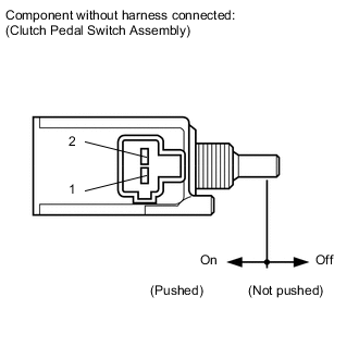
INSPECT CLUTCH PEDAL SWITCH
-

Disconnect the clutch pedal switch assembly connector.
-
Measure the resistance according to the value(s) in the table below.
Standard Resistance Tester Connection Switch Condition Specified Condition 1 - 2 Pin not pushed 10 kΩ or higher Pin pushed Below 1 Ω -
Reconnect the clutch pedal switch assembly connector.
OK
INSPECT IGNITION SWITCH ASSEMBLY Click here
NG
REPLACE CLUTCH PEDAL SWITCH Click here
-
-
CHECK HARNESS AND CONNECTOR (ST RELAY - PARK/NEUTRAL POSITION SWITCH)
-
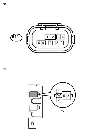
Text in Illustration *1 No. 1 Relay Block *2 ST Relay *a Front view of wire harness connector
(to Park/Neutral Position Switch)
Remove the ST relay from the No. 1 relay block.
-
Disconnect the park/neutral position switch connector.
-
Measure the resistance according to the value(s) in the table below.
Standard Resistance (Check for Open) Tester Connection Condition Specified Condition ST relay terminal 1 - B14-9 Always Below 1 Ω Standard Resistance (Check for Short) Tester Connection Condition Specified Condition ST relay terminal 1 or B14-9 - Body ground Always 10 kΩ or higher -
Reinstall the ST relay.
-
Reconnect the park/neutral position switch connector.
NG
REPAIR OR REPLACE HARNESS OR CONNECTOR (ST RELAY - PARK/NEUTRAL POSITION SWITCH)
OK
-
-
CHECK HARNESS AND CONNECTOR (PARK/NEUTRAL POSITION SWITCH - IGNITION SWITCH ASSEMBLY)
-
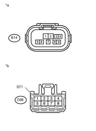
Text in Illustration *a Front view of wire harness connector
(to Park/Neutral Position Switch)
*b Front view of wire harness connector
(to Ignition Switch Assembly)
Disconnect the park/neutral position switch connector.
-
Disconnect the ignition switch assembly connector.
-
Measure the resistance according to the value(s) in the table below.
Standard Resistance (Check for Open) Tester Connection Condition Specified Condition B14-4 - D98-1 (ST1) Always Below 1 Ω Standard Resistance (Check for Short) Tester Connection Condition Specified Condition B14-4 or D98-1 (ST1) - Body ground Always 10 kΩ or higher -
Reconnect the park/neutral position switch connector.
-
Reconnect the ignition switch assembly connector.
NG
REPAIR OR REPLACE HARNESS OR CONNECTOR (PARK/NEUTRAL POSITION SWITCH - IGNITION SWITCH ASSEMBLY)
OK
-
-
INSPECT PARK/NEUTRAL POSITION SWITCH ASSEMBLY
-
Inspect the park/neutral position switch assembly Click here.
NG
REPLACE PARK/NEUTRAL POSITION SWITCH ASSEMBLY Click here
OK
-
-
INSPECT IGNITION SWITCH ASSEMBLY
-
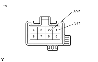
Text in Illustration *a Component without harness connected
(Ignition Switch Assembly)
Disconnect the ignition switch assembly connector.
-
Measure the resistance according to the value(s) in the table below.
Standard Resistance Tester Connection Ignition Switch Position Specified Condition All terminals Off 10 kΩ or higher 2 (AM1) - 1 (ST1) START Below 1 Ω -
Reconnect the ignition switch assembly connector.
OK
REPAIR OR REPLACE HARNESS OR CONNECTOR (IGNITION SWITCH ASSEMBLY - BATTERY)
NG
REPLACE IGNITION SWITCH ASSEMBLY Click here
-
-
READ VALUE USING INTELLIGENT TESTER (STARTER SIGNAL)
-
Connect the intelligent tester to the DLC3.
-
Turn the ignition switch to ON.
-
Turn the tester on.
-
Enter the following menus: Powertrain / Engine and ECT / Data List / Starter Signal.
-
Read the value.
OK Ignition Switch Position Starter Signal ON OFF START ON
OK
PROCEED TO NEXT SUSPECTED AREA SHOWN IN PROBLEM SYMPTOMS TABLE Click here
NG
-
-
CHECK STARTER RELAY (POWER SOURCE)
-
Text in Illustration *1 No. 1 Relay Block *2 ST Relay Remove the ST relay from the No. 1 relay block.
-
Measure the voltage according to the value(s) in the table below.
Standard Voltage Tester Connection Condition Specified Condition ST relay terminal 1 - Body ground Engine cranking 11 to 14 V Tech Tips
The engine does not crank because the relay is not installed.
Result Result Proceed to OK A NG (for Manual transaxle) B NG (for Automatic transaxle) C -
Reinstall the ST relay.
B
CHECK HARNESS AND CONNECTOR (ST RELAY - CLUTCH PEDAL SWITCH ASSEMBLY) Click here
C
CHECK HARNESS AND CONNECTOR (ST RELAY - PARK/NEUTRAL POSITION SWITCH) Click here
A
-
-
INSPECT STARTER RELAY
-
Remove the ST relay from the No. 1 relay block.
-
Measure the resistance according to the value(s) in the table below.
Standard Resistance Tester Connection Condition Specified Condition 3 - 5 Battery voltage not applied between terminals 1 and 2 10 kΩ or higher 3 - 5 Battery voltage applied between terminals 1 and 2 Below 1 Ω -
Reinstall the ST relay.
NG
REPLACE STARTER RELAY
OK
-
-
CHECK HARNESS AND CONNECTOR (ST RELAY - BODY GROUND)
-
Text in Illustration *1 No. 1 Relay Block *2 ST Relay Remove the ST relay from the No. 1 relay block.
-
Measure the resistance according to the value(s) in the table below.
Standard Resistance Tester Connection Condition Specified Condition ST relay terminal 2 - Body ground Always Below 1 Ω -
Reinstall the ST relay.
OK
REPAIR OR REPLACE HARNESS OR CONNECTOR (ECM - CLUTCH PEDAL SWITCH ASSEMBLY OR PARK/NEUTRAL POSITION SWITCH ASSEMBLY)
NG
REPAIR OR REPLACE HARNESS OR CONNECTOR (ST RELAY - BODY GROUND)
-
-
CHECK HARNESS AND CONNECTOR (ST RELAY - CLUTCH PEDAL SWITCH ASSEMBLY)
-

Text in Illustration *1 No. 1 Relay Block *2 ST Relay *a Front view of wire harness connector
(to Clutch Pedal Switch Assembly)
Remove the ST relay from the No. 1 relay block.
-
Disconnect the clutch pedal switch assembly connector.
-
Measure the resistance according to the value(s) in the table below.
Standard Resistance (Check for Open) Tester Connection Condition Specified Condition ST relay terminal 1 - A3-1 Always Below 1 Ω Standard Resistance (Check for Short) Tester Connection Condition Specified Condition ST relay terminal 1 or A3-1 - Body ground Always 10 kΩ or higher -
Reinstall the ST relay.
-
Reconnect the clutch pedal switch assembly connector.
NG
REPAIR OR REPLACE HARNESS OR CONNECTOR (ST RELAY - CLUTCH PEDAL SWITCH ASSEMBLY)
OK
-
-
CHECK HARNESS AND CONNECTOR (CLUTCH PEDAL SWITCH ASSEMBLY - POWER MANAGEMENT CONTROL ECU)
-
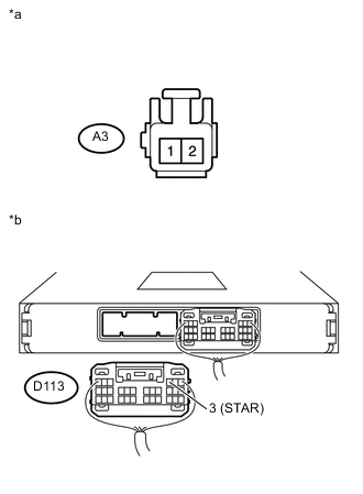
Text in Illustration *a Front view of wire harness connector
(to Clutch Pedal Switch Assembly)
*b Rear view of wire harness connector
(to Power Management Control ECU)
Disconnect the clutch pedal switch assembly connector.
-
Disconnect the power management control ECU connector.
-
Measure the resistance according to the value(s) in the table below.
Standard Resistance (Check for Open) Tester Connection Condition Specified Condition A3-2 - D113-3 (STAR) Always Below 1 Ω Standard Resistance (Check for Short) Tester Connection Condition Specified Condition A3-2 or D113-3 (STAR) - Body ground Always 10 kΩ or higher -
Reconnect the clutch pedal switch assembly connector.
-
Reconnect the power management control ECU connector.
NG
REPAIR OR REPLACE HARNESS OR CONNECTOR (CLUTCH PEDAL SWITCH ASSEMBLY - POWER MANAGEMENT CONTROL ECU)
OK
-
-
INSPECT CLUTCH PEDAL SWITCH
-
Disconnect the clutch pedal switch assembly connector.
-
Measure the resistance according to the value(s) in the table below.
Standard Resistance Tester Connection Switch Condition Specified Condition 1 - 2 Pin not pushed 10 kΩ or higher Pin pushed Below 1 Ω -
Reconnect the clutch pedal switch assembly connector.
OK
GO TO ENTRY AND START SYSTEM Click here
NG
REPLACE CLUTCH PEDAL SWITCH Click here
-
-
CHECK HARNESS AND CONNECTOR (ST RELAY - PARK/NEUTRAL POSITION SWITCH)
-
Text in Illustration *1 No. 1 Relay Block *2 ST Relay *a Front view of wire harness connector
(to Park/Neutral Position Switch)
Remove the ST relay from the No. 1 relay block.
-
Disconnect the park/neutral position switch connector.
-
Measure the resistance according to the value(s) in the table below.
Standard Resistance (Check for Open) Tester Connection Condition Specified Condition ST relay terminal 1 - B14-9 Always Below 1 Ω Standard Resistance (Check for Short) Tester Connection Condition Specified Condition ST relay terminal 1 or B14-9 - Body ground Always 10 kΩ or higher -
Reinstall the ST relay.
-
Reconnect the park/neutral position switch connector.
NG
REPAIR OR REPLACE HARNESS OR CONNECTOR (ST RELAY - PARK/NEUTRAL POSITION SWITCH)
OK
-
-
CHECK HARNESS AND CONNECTOR (PARK/NEUTRAL POSITION SWITCH - POWER MANAGEMENT CONTROL ECU)
-
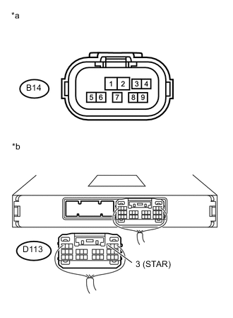
Text in Illustration *a Front view of wire harness connector
(to Park/Neutral Position Switch)
*b Rear view of wire harness connector
(to Power Management Control ECU)
Disconnect the park/neutral position switch connector.
-
Disconnect the power management control ECU connector.
-
Measure the resistance according to the value(s) in the table below.
Standard Resistance (Check for Open) Tester Connection Condition Specified Condition B14-4 - D113-3 (STAR) Always Below 1 Ω Standard Resistance (Check for Short) Tester Connection Condition Specified Condition B14-4 or D113-3 (STAR) - Body ground Always 10 kΩ or higher -
Reconnect the park/neutral position switch connector.
-
Reconnect the power management control ECU connector.
NG
REPAIR OR REPLACE HARNESS OR CONNECTOR (PARK/NEUTRAL POSITION SWITCH - POWER MANAGEMENT CONTROL ECU)
OK
-
-
INSPECT PARK/NEUTRAL POSITION SWITCH ASSEMBLY
-
Inspect the park/neutral position switch assembly Click here.
OK
GO TO ENTRY AND START SYSTEM Click here
NG
REPLACE PARK/NEUTRAL POSITION SWITCH ASSEMBLY Click here
-