ECD SYSTEM, Diagnostic DTC:P2237, P2238, P2239, P2252, P2253
| DTC Code | DTC Name |
|---|---|
| P2237 | Oxygen (A/F) Sensor Pumping Current Circuit / Open (Bank 1 Sensor 1) |
| P2238 | Oxygen (A/F) Sensor Pumping Current Circuit Low (Bank 1 Sensor 1) |
| P2239 | Oxygen (A/F) Sensor Pumping Current Circuit High (Bank 1 Sensor 1) |
| P2252 | Oxygen (A/F) Sensor Reference Ground Circuit Low (Bank 1 Sensor 1) |
| P2253 | Oxygen (A/F) Sensor Reference Ground Circuit High (Bank 1 Sensor 1) |
DESCRIPTION
Tech Tips
-
For more information on the A/F sensor and TOYOTA D-CAT* Click here.
-
If P2237, P2238 and/or P2239 is present, refer to the DTC table for TOYOTA D-CAT system Click here.
-
These DTCs are recorded when the A/F sensor has a malfunction, although the title is the oxygen sensor.
*: Diesel Clean Advanced Technology.
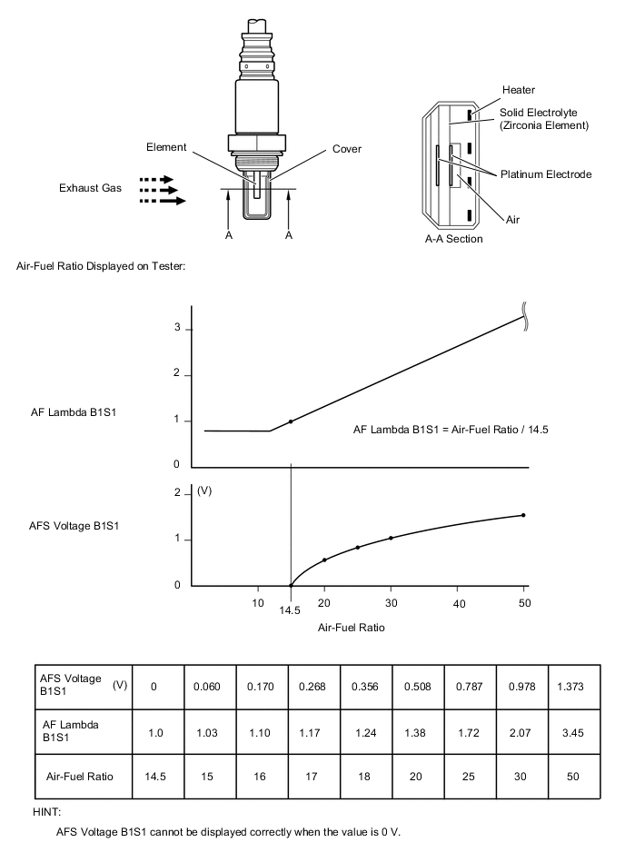
The A/F sensor has the characteristic of providing output voltage which is proportional to the air-fuel ratio. The A/F sensor output voltage*1 is used by the ECM to control the air-fuel ratio.
The A/F sensor is located after the DPNR*2 catalytic converter. This sensor has been developed based on the structure and technology of a sensor that is being used for gasoline engines. The cover portion of the sensor has been changed for use in the diesel engine with TOYOTA D-CAT in order to eliminate the influence of the sensor temperature and particulate matter (PM).
In order to reduce both PM and nitrogen oxides (NOx), the ECM adjusts the air-fuel ratio to slightly rich (but it is lean compared with the stoichiometric air-fuel ratio) based on signals from the A/F sensor. When the ECM performs DPNR catalyst regeneration by adding fuel using the exhaust fuel addition injector, the air-fuel ratio is also properly adjusted using the sensor.
*1: The voltage value changes inside the ECM only.
*2: Diesel Particulate-NOx Reduction system.
Tech Tips
The ECM provides a pulse width modulated control circuit to adjust current through the heater. The A/F sensor heater circuit uses a relay on the B+ side of the circuit.
| DTC Detection Drive Pattern | DTC Detection Condition | Trouble Area |
|---|---|---|
|
When either of the following conditions is met (1 trip detection logic):
|
Main trouble area: Open in A/F sensor circuit
|
| DTC Detection Drive Pattern | DTC Detection Condition | Trouble Area |
|---|---|---|
| Ignition switch ON for 7 seconds | A/F sensor circuit low (bank 1 sensor 1) (1 trip detection logic) |
Main trouble area: Open in A/F sensor circuit
|
| DTC Detection Drive Pattern | DTC Detection Condition | Trouble Area |
|---|---|---|
| Ignition switch ON for 7 seconds | A/F sensor circuit high (bank 1 sensor 1) (1 trip detection logic) |
Main trouble area: Short in A/F sensor circuit
|
| DTC Detection Drive Pattern | DTC Detection Condition | Trouble Area |
|---|---|---|
| Ignition switch ON for 7 seconds | A/F sensor circuit low (bank 1 sensor 1) (1 trip detection logic) |
Main trouble area: Open in A/F sensor circuit
|
| DTC Detection Drive Pattern | DTC Detection Condition | Trouble Area |
|---|---|---|
| Ignition switch ON for 7 seconds | A/F sensor circuit high (bank 1 sensor 1) (1 trip detection logic) |
Main trouble area: Short in A/F sensor circuit
|
| DTC No. | Data List |
|---|---|
| P2237 |
|
| P2238 | |
| P2239 | |
| P2252 | |
| P2253 |
MONITOR DESCRIPTION
The A/F sensor outputs a voltage in proportion to the air-fuel ratio. If impedance (alternating current resistance) or voltage output of the sensor deviates greatly from the standard range, the ECM interprets this as an open or short malfunction of the A/F sensor circuit.
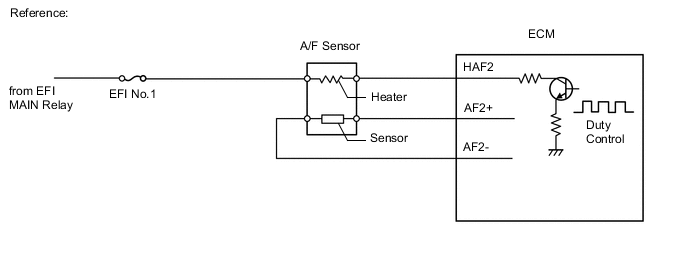
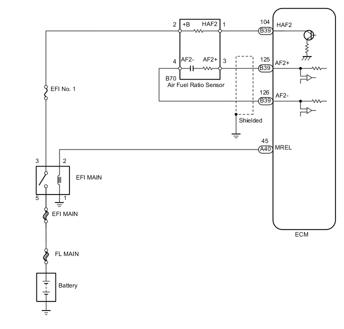
WIRING DIAGRAM
CAUTION / NOTICE / HINT
Note
After replacing the ECM, the new ECM needs registration (See page ) and initialization Click here.
PROCEDURE
-
CHECK HARNESS AND CONNECTOR (A/F SENSOR - ECM)
-
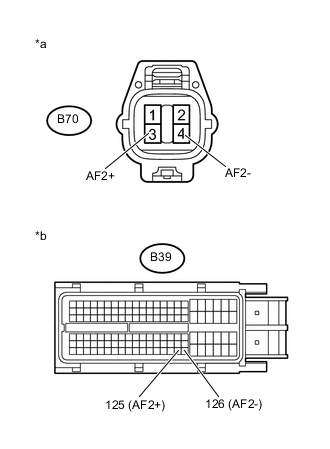
Text in Illustration *a Front view of wire harness connector
(to A/F Sensor)
*b Front view of wire harness connector
(to ECM)
Disconnect the A/F sensor connector.
-
Disconnect the ECM connector.
-
Measure the resistance according to the value(s) in the table below.
Standard Resistance (Check for Open) Tester Connection Condition Specified Condition B70-3 (AF2+) - B39-125 (AF2+) Always Below 1 Ω B70-4 (AF2-) - B39-126 (AF2-) Always Below 1 Ω Standard Resistance (Check for Short) Tester Connection Condition Specified Condition B70-3 (AF2+) or B39-125 (AF2+) - Body ground Always 10 kΩ or higher B70-4 (AF2-) or B39-126 (AF2-) - Body ground Always 10 kΩ or higher -
Reconnect the A/F sensor connector.
-
Reconnect the ECM connector.
NG 
REPAIR OR REPLACE HARNESS OR CONNECTOR Click here
OK 
-
-
REPLACE AIR FUEL RATIO SENSOR
-
Replace the air fuel ratio sensor Click here.
NEXT
-
-
CONFIRM WHETHER MALFUNCTION HAS BEEN SUCCESSFULLY REPAIRED
-
Warm up the engine.
-
Connect the intelligent tester to the DLC3.
-
Turn the ignition switch to ON.
-
Turn the tester on.
-
Clear the DTCs Click here.
-
Drive the vehicle at 50 km/h (30 mph) or more for a total of 300 seconds or more.
Tech Tips
Make sure that the exhaust gas temperature (Exhaust Temperature B1S1) is 200°C (392°F) or higher.
-
Confirm that the DTC is not output again.
OK 
END
NG
-
-
REPLACE ECM
-
Replace the ECM Click here.
NEXT
CONFIRM WHETHER MALFUNCTION HAS BEEN SUCCESSFULLY REPAIRED Click here
-
-
REPAIR OR REPLACE HARNESS OR CONNECTOR
-
Repair or replace the harness or connector.
NEXT
-
-
CONFIRM WHETHER MALFUNCTION HAS BEEN SUCCESSFULLY REPAIRED
-
Warm up the engine.
-
Connect the intelligent tester to the DLC3.
-
Turn the ignition switch to ON.
-
Turn the tester on.
-
Clear the DTCs Click here.
-
Drive the vehicle at 50 km/h (30 mph) or more for a total of 300 seconds or more.
Tech Tips
Make sure that the exhaust gas temperature (Exhaust Temperature B1S1) is 200°C (392°F) or higher.
-
Confirm that the DTC is not output again.
NEXT
END
-