ECD SYSTEM, Diagnostic DTC:P0545, P0546, P2032, P2033
| DTC Code | DTC Name |
|---|---|
| P0545 | Exhaust Gas Temperature Sensor Circuit Low (Bank 1 Sensor 1) |
| P0546 | Exhaust Gas Temperature Sensor Circuit High (Bank 1 Sensor 1) |
| P2032 | Exhaust Gas Temperature Sensor Circuit Low (Bank 1 Sensor 2) |
| P2033 | Exhaust Gas Temperature Sensor Circuit High (Bank 1 Sensor 2) |
DESCRIPTION
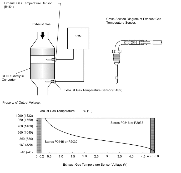
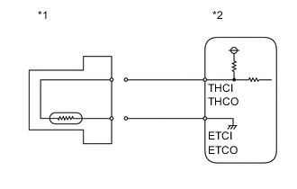
The exhaust gas temperature sensors are installed before and after the DPNR* catalytic converter to sense the exhaust gas temperature.
A thermistor built into the sensor changes its resistance value according to the exhaust gas temperature. The lower the exhaust gas temperature, the higher the thermistor resistance value. The higher the exhaust gas temperature, the lower the thermistor resistance value.
The exhaust gas temperature sensor is connected to the ECM. The 5 V power source voltage in the ECM is applied to the exhaust gas temperature sensor from terminal THCI (B1S1) and THCO (B1S2) via resistor R.
Resistor R and the exhaust gas temperature sensor are connected in series. When the resistance value of the exhaust gas temperature sensor changes in accordance with the exhaust gas temperature, the voltage at terminals THCI (B1S1) and THCO (B1S2) also changes. When DPNR catalyst regeneration is needed, the ECM operates the exhaust fuel addition injector to obtain target upstream temperature of the DPNR catalytic converter as monitored through sensor 1. In addition, the ECM monitors the temperature increase of the DPNR catalytic converter using sensor 2.
*: Diesel Particulate-NOx Reduction system.
| DTC Detection Drive Pattern | DTC Detection Condition | Trouble Area |
|---|---|---|
| Idle the engine for 3 seconds after warming up the engine (the engine coolant temperature is 70°C (158°F) or higher) and allowing 11 minutes to elapse after starting the engine. | Sensor 1 output is below 0.2 V for 3 seconds or more. (1 trip detection logic) |
|
| DTC Detection Drive Pattern | DTC Detection Condition | Trouble Area |
|---|---|---|
| Idle the engine for 3 seconds after warming up the engine (the engine coolant temperature is 70°C (158°F) or higher) and allowing 11 minutes to elapse after starting the engine. | Sensor 1 output is higher than 4.95 V for 3 seconds or more. (1 trip detection logic) |
|
| DTC Detection Drive Pattern | DTC Detection Condition | Trouble Area |
|---|---|---|
| Idle the engine for 3 seconds after warming up the engine (the engine coolant temperature is 70°C (158°F) or higher) and allowing 11 minutes to elapse after starting the engine. | Sensor 2 output is below 0.2 V for 3 seconds or more. (1 trip detection logic) |
|
| DTC Detection Drive Pattern | DTC Detection Condition | Trouble Area |
|---|---|---|
| Idle the engine for 3 seconds after warming up the engine (the engine coolant temperature is 70°C (158°F) or higher) and allowing 11 minutes to elapse after starting the engine. | Sensor 2 output is higher than 4.95 V for 3 seconds or more. (1 trip detection logic) |
|
| DTC No. | Data List |
|---|---|
| P0545 | Exhaust Temperature B1S1 |
| P0546 | |
| P2032 | Exhaust Temperature B1S2 |
| P2033 |
Tech Tips
-
DTC P20CF (Exhaust fuel addition injector malfunction) may be stored if there is an open malfunction in an exhaust gas temperature sensor circuit.
-
Sensor 1 the represents sensor located upstream in front of the DPNR catalytic converter.
-
Sensor 2 the represents sensor located downstream behind the DPNR catalytic converter.
-
After confirming DTC P0545, P0546, P2032, and/or P2033, check the upstream and downstream exhaust gas temperature in "Powertrain / Engine and ECT / Exhaust Temperature B1S1 and Exhaust Temperature B1S2" using the intelligent tester.
| Condition | Exhaust Gas Temperature | Exhaust Gas Temperature Sensor Condition |
|---|---|---|
| Idling after warm-up | Constant at between 50 and 700°C (122 and 1292°F) | Normal |
| 0°C (32°F) | Open circuit | |
| 1000°C (1832°F) | Short circuit |
MONITOR DESCRIPTION
The ECM constantly monitors the output voltages from the exhaust gas temperature sensors in order to detect problems with the sensors. When the sensor output voltage deviates from the normal operating range (between 0.2 V and 4.95 V) for more than 3 seconds after the engine is warmed up, the ECM interprets this as malfunction of the sensor circuit and illuminates the MIL.
WIRING DIAGRAM
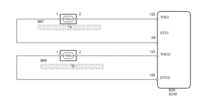
| *a | Exhaust Gas Temperature Sensor (B1S1) |
| *b | Exhaust Gas Temperature Sensor (B1S2) |
CAUTION / NOTICE / HINT
Note
After replacing the ECM, the new ECM needs registration (See page ) and initialization Click here.
Tech Tips
If DTC P2033 is stored and the exhaust gas temperature sensor (B1S2) circuit is not malfunctioning, check if the DPNR catalytic converter has melted as DTC P2033 may be stored when the DPNR catalytic converter melts and the exhaust gas temperature sensor (B1S2) is exposed to high temperatures.
PROCEDURE
-
READ VALUE USING INTELLIGENT TESTER (EXHAUST TEMPERATURE)
-
Connect the intelligent tester to the DLC3.
-
Turn the ignition switch to ON and turn the intelligent tester on.
-
Enter the following menus: Powertrain / Engine and ECT / Data List / Exhaust Temperature B1S1 and Exhaust Temperature B1S2.
-
Read the value.
Standard Same as the actual exhaust gas temperature (50 to 700°C [122 to 1292°F] during idling after warm-up), and varies after an engine speed of 3000 rpm is maintained for 1 minute. Result Temperature Displayed Proceed to 0°C (32°F) (After warming up the engine) A 1000°C (1832°F) B OK: Same as the actual exhaust gas temperature (50 to 700°C [122 to 1292°F] during idling after warm-up), and varies after maintaining an engine speed of 3000 rpm for 1 minute after accelerating the engine from idling to 3000 rpm C Tech Tips
-
If there is a short circuit, the intelligent tester will indicate 0°C (32°F).
-
If there is an open circuit, the intelligent tester will indicate 1000°C (1832°F).
-
B 
READ VALUE USING INTELLIGENT TESTER (CHECK FOR SHORT IN WIRE HARNESS) Click here
C
CONFIRM WHETHER MALFUNCTION HAS BEEN SUCCESSFULLY REPAIRED Click here
A 
-
-
READ VALUE USING INTELLIGENT TESTER (CHECK FOR OPEN IN WIRE HARNESS)
-
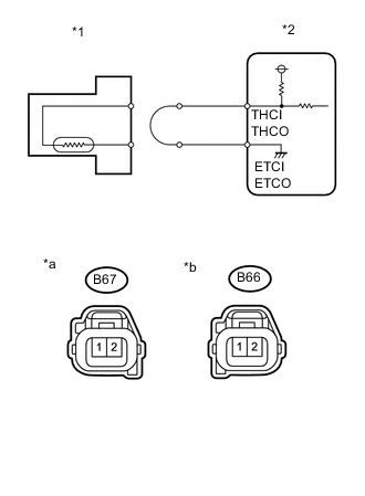
Text in Illustration *1 Exhaust Gas Temperature Sensor *2 ECM *a Front view of wire harness connector
(to Exhaust Gas Temperature Sensor (B1S1))
*b Front view of wire harness connector
(to Exhaust Gas Temperature Sensor (B1S2))
Disconnect the B67 or B66 exhaust gas temperature sensor connector.
-
Connect terminals 1 and 2 of the exhaust gas temperature sensor wire harness side connector.
-
Connect the intelligent tester to the DLC3.
-
Turn the ignition switch to ON and turn the intelligent tester on.
-
Enter the following menus: Powertrain / Engine and ECT / Data List / Exhaust Temperature B1S1 and Exhaust Temperature B1S2.
-
Read the value.
Standard 1000°C (1832°F) -
Reconnect the exhaust gas temperature sensor connector.
NG
CHECK HARNESS AND CONNECTOR (EXHAUST GAS TEMPERATURE SENSOR - ECM) Click here
OK
-
-
REPLACE EXHAUST GAS TEMPERATURE SENSOR
-
Replace the exhaust gas temperature sensor Click here.
NEXT
CONFIRM WHETHER MALFUNCTION HAS BEEN SUCCESSFULLY REPAIRED Click here
-
-
CHECK HARNESS AND CONNECTOR (EXHAUST GAS TEMPERATURE SENSOR - ECM)
-
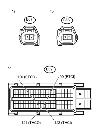
Text in Illustration *a Front view of wire harness connector
(to Exhaust Gas Temperature Sensor (B1S1))
*b Front view of wire harness connector
(to Exhaust Gas Temperature Sensor (B1S2))
*c Front view of wire harness connector
(to ECM)
Disconnect the exhaust gas temperature sensor connector.
-
Disconnect the ECM connector.
-
Measure the resistance according to the value(s) in the table below.
Standard Resistance Tester Connection Condition Specified Condition B67-2 - B39-122 (THCI) Always Below 1 Ω B67-1 - B39-99 (ETCI) Always Below 1 Ω B66-2 - B39-121 (THCO) Always Below 1 Ω B66-1 - B39-120 (ETCO) Always Below 1 Ω -
Reconnect the exhaust gas temperature sensor connector.
-
Reconnect the ECM connector.
NG
REPAIR OR REPLACE HARNESS OR CONNECTOR Click here
OK
-
-
REPLACE ECM
-
Replace the ECM Click here.
NEXT
CONFIRM WHETHER MALFUNCTION HAS BEEN SUCCESSFULLY REPAIRED Click here
-
-
READ VALUE USING INTELLIGENT TESTER (CHECK FOR SHORT IN WIRE HARNESS)
-
Text in Illustration *1 Exhaust Gas Temperature Sensor *2 ECM Disconnect the B67 or B66 exhaust gas temperature sensor connector.
-
Connect the intelligent tester to the DLC3.
-
Turn the ignition switch to ON and turn the intelligent tester on.
-
Enter the following menus: Powertrain / Engine and ECT / Data List / Exhaust Temperature B1S1 and Exhaust Temperature B1S2.
-
Read the value.
Standard 0°C (32°F) -
Reconnect the exhaust gas temperature sensor connector.
-
Reconnect the exhaust gas temperature sensor connector.
NG
CHECK HARNESS AND CONNECTOR (EXHAUST GAS TEMPERATURE SENSOR - ECM) Click here
OK
-
-
REPLACE EXHAUST GAS TEMPERATURE SENSOR
-
Replace the exhaust gas temperature sensor Click here.
NEXT
CONFIRM WHETHER MALFUNCTION HAS BEEN SUCCESSFULLY REPAIRED Click here
-
-
CHECK HARNESS AND CONNECTOR (EXHAUST GAS TEMPERATURE SENSOR - ECM)
-
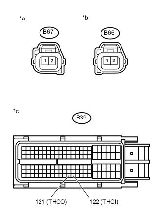
Text in Illustration *a Front view of wire harness connector
(to Exhaust Gas Temperature Sensor (B1S1))
*b Front view of wire harness connector
(to Exhaust Gas Temperature Sensor (B1S2))
*c Front view of wire harness connector
(to ECM)
Disconnect the exhaust gas temperature sensor connector.
-
Disconnect the ECM connector.
-
Measure the resistance according to the value(s) in the table below.
Standard Resistance Tester Connection Condition Specified Condition B67-2 or B39-122 (THCI) - Body ground Always 10 kΩ or higher B66-2 or B39-121 (THCO) - Body ground Always 10 kΩ or higher -
Reconnect the exhaust gas temperature sensor connector.
-
Reconnect the ECM connector.
NG
REPAIR OR REPLACE HARNESS OR CONNECTOR Click here
OK
-
-
REPLACE ECM
-
Replace the ECM Click here.
NEXT
CONFIRM WHETHER MALFUNCTION HAS BEEN SUCCESSFULLY REPAIRED Click here
-
-
REPAIR OR REPLACE HARNESS OR CONNECTOR
-
Repair or replace the harness or connector.
NEXT
-
-
CONFIRM WHETHER MALFUNCTION HAS BEEN SUCCESSFULLY REPAIRED
-
Connect the intelligent tester to the DLC3.
-
Clear the DTCs Click here.
-
Start the engine.
-
Idle the engine for 3 seconds or more after warming up the engine (the engine coolant temperature is 70°C (159°F) or higher) and allowing 11 minutes to elapse after starting the engine.
-
Enter the following menus: Powertrain / Engine and ECT / DTC.
-
Confirm that the DTC is not output again.
NEXT 
END
-