ECD SYSTEM(for DPF), Diagnostic DTC:P1271, P1272
| DTC Code | DTC Name |
|---|---|
| P1271 | Fuel Regulator Circuit Malfunction (EDU Drive) |
| P1272 | Fuel Pressure Regulator Malfunction |
DESCRIPTION
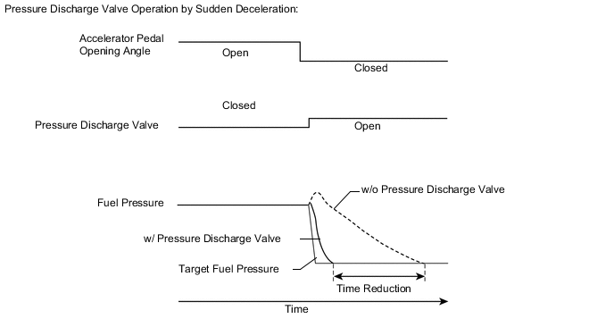
The ECM controls the internal fuel pressure of the common rail by opening and closing the pressure discharge valve. When sudden deceleration occurs, the internal fuel pressure will temporarily become higher than usual and combustion noise may result. Therefore the ECM will open the valve temporarily to discharge the excess pressure inside the common rail. Also, the pressure discharge valve opens when the ignition switch is turned off to allow prompt discharge of the common rail internal pressure and so that the engine stops smoothly.
Tech Tips
-
For more information on the pressure discharge valve and common rail system Click here.
-
For more information on the EDU Click here.
-
If P1271 and/or P1272 is present, refer to the DTC chart for the fuel system Click here.
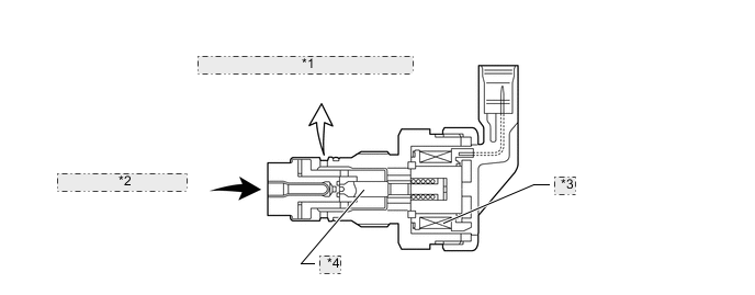
| *1 | Return to Fuel Tank (Low Pressure) |
| *2 | From Common Rail (High Pressure) |
| *3 | Solenoid |
| *4 | Valve |
| DTC Detection Drive Pattern | DTC Detection Condition | Trouble Area |
|---|---|---|
| Ignition switch ON to off and Drive the vehicle at 50 km/h (31 mph) in third gear, and then decelerate by releasing the accelerator pedal |
When either condition below is met (1 trip detection logic):
|
|
| DTC Detection Drive Pattern | DTC Detection Condition | Trouble Area |
|---|---|---|
| Ignition switch ON to off | Pressure discharge valve does not open. Actual pressure decreasing rate deviates from the simulated pressure decreasing rate after the ignition switch is turned off. (2 trip detection logic) |
|
| DTC No. | Data List |
|---|---|
| P1271 |
|
| P1272 |
Tech Tips
-
After confirming DTC P1271 and/or P1272, check the fuel pressure inside the common rail in "Powertrain / Engine and ECT / Data List / Common Rail Pressure" using the intelligent tester.
-
P1271:
After clearing the DTC, drive the vehicle at 50 km/h (31 mph) in third gear, and then decelerate by releasing the accelerator pedal. Check that P1271 is not present.
-
P1272:
After clearing the DTC, start and stop the engine twice (wait 30 seconds or more after turning the ignition switch off before starting the engine the second time), and then confirm that P1272 is not stored.
| Engine Speed | Fuel Pressure (kPa) |
|---|---|
| Idling | Common Rail Pressure is within +/-5000 kPa of Target Common Rail Pressure |
| 2500 rpm (No engine load) |
| Condition | Common Rail Pressure (Idling) | Common Rail Pressure (1 Second after Engine Stopped) |
|---|---|---|
| Pressure discharge valve normal | 35000 kPa | 170 kPa |
| Open in pressure discharge valve circuit | 34000 kPa | 34300 kPa |
MONITOR DESCRIPTION
- P1271 (Open or short in pressure discharge valve circuit):
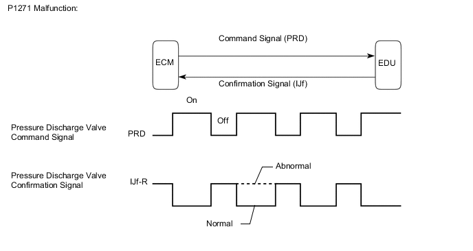
This DTC will be set if there is no valve opening confirmation (IJf) signal sent from the EDU to the ECM, despite the ECM has commanded the EDU to open the pressure discharge valve. This DTC refers to an open or short circuit malfunction of the pressure discharge valve circuit, not a malfunction in which a valve is stuck open or closed.
The EDU monitors the current supplied to the pressure discharge valve to verify that the current flows into the valve. If the current exceeds the specified level, the EDU interprets this as the IJf signal being low. If this DTC is stored, the ECM enters the fail-safe mode and limits engine power. The fail-safe mode continues until the ignition switch is turned off.
- P1272 (Closed malfunction of the pressure discharge valve):
The pressure discharge valve will open and discharge the internal fuel pressure from the common rail to the fuel tank when the ignition switch is turned off. In this event, the ECM compares the actual drop rate of the internal fuel pressure and the target drop rate. If the ECM judges that the actual drop rate is smaller than the target, the ECM then judges that the valve is stuck closed and stores this DTC. This DTC will be stored if the internal fuel pressure does not drop to the target after the ignition switch has been turned off.
If this DTC is stored, the ECM enters fail-safe mode and limits engine power. The fail-safe mode continues until the ignition switch is turned off.
MONITOR STRATEGY
| Required sensors | EDU |
| Frequency of operation | Continuous |
| Duration | 3 seconds |
| MIL operation | 1 driving cycle |
| Required sensors | Fuel pressure sensor |
| Frequency of operation | Once per driving cycle |
| Duration | 1 second |
| MIL operation | 2 driving cycles |
TYPICAL ENABLING CONDITIONS
| Specification |
|---|
| The vehicle is driven at 50 km/h (31 mph) in 3rd gear, and then decelerated by complete release of the accelerator pedal 3 times. |
| Item | Specification | |
|---|---|---|
| Minimum | Maximum | |
| Fuel pressure | 30000 kPa (306 kgf/cm2, 4350 psi) |
- |
| Fuel temperature | 0°C (32°F) | - |
| Battery voltage | 11 V | - |
| The monitor will not run if the fuel pressure sensor, pressure discharge valve circuit or fuel temperature sensor is malfunctioning. | ||
TYPICAL MALFUNCTION THRESHOLDS
| Specification |
|---|
| There are no confirmation signals from the EDU for a specific number of times consecutively, despite the ECM sending command signals regularly during deceleration. |
| Specification |
|---|
| The internal pressure stays beyond the specified level after the ignition switch is turned off. |
WIRING DIAGRAM
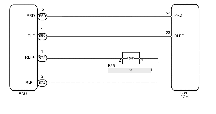
| *a | Pressure Discharge Valve |
CAUTION / NOTICE / HINT
Note
After replacing the ECM, the new ECM needs registration (See page ) and initialization Click here.
Tech Tips
-
After completing repairs, confirm that P1271 and/or P1272 does not recur.
-
If P0200 and P1271 are present simultaneously, there is an open in the INJF wire harness between the EDU and ECM, or there is an open in the wire harness for both an injector and the pressure discharge valve.
-
Read freeze frame data using the intelligent tester. Freeze frame data records the engine condition when malfunctions are detected. When troubleshooting, freeze frame data can help determine if the vehicle was moving or stationary, if the engine was warmed up or not, and other data from the time the malfunction occurred.
PROCEDURE
-
CHECK IF DTC OUTPUT RECURS
-
Connect the intelligent tester to the DLC3.
-
Clear the DTCs Click here.
-
Turn the ignition switch off for 30 seconds or more.
-
Turn the ignition switch to ON.
-
Drive the vehicle at 50 km/h (31 mph) in 3rd gear, and then decelerate by completely releasing the accelerator pedal. Perform this 3 times.
-
Enter the following menus: Powertrain / Engine and ECT / DTC.
-
Read the pending DTCs.
Result Result Proceed to P1272 A P1271 B P1271 and P1272 B Other DTCs output C
B 
INSPECT PRESSURE DISCHARGE VALVE Click here
C 
GO TO DTC CHART Click here
A 
-
-
CHECK COMMON RAIL ASSEMBLY (PRESSURE DISCHARGE VALVE OPERATION)
-
Inspect the common rail assembly Click here.
OK
CONFIRM WHETHER MALFUNCTION HAS BEEN SUCCESSFULLY REPAIRED Click here
NG
REPLACE COMMON RAIL ASSEMBLY Click here
-
-
INSPECT PRESSURE DISCHARGE VALVE
-
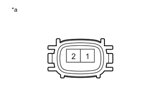
Text in Illustration *a Component without harness connected
(Pressure Discharge Valve)
Disconnect the pressure discharge valve connector.
-
Measure the resistance according to the value(s) in the table below.
Standard Resistance Condition Specified Condition 20°C (68°F) 0.96 to 1.16 Ω -
Reconnect the pressure discharge valve connector.
NG
REPLACE COMMON RAIL ASSEMBLY Click here
OK
-
-
CHECK HARNESS AND CONNECTOR (PRESSURE DISCHARGE VALVE - EDU)
-
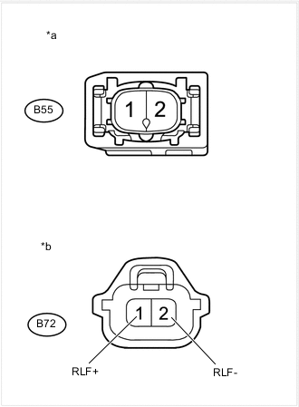
Text in Illustration *a Front view of wire harness connector
(to Pressure Discharge Valve)
*b Front view of wire harness connector
(to EDU)
Disconnect the EDU connector.
-
Disconnect the pressure discharge valve connector.
-
Measure the resistance according to the value(s) in the table below.
Standard Resistance Tester Connection Condition Specified Condition B55-2 - B72-1 (RLF+) Always Below 1 Ω B55-1 - B72-2 (RLF-) Always Below 1 Ω B55-2 or B72-1 (RLF+) - Body ground Always 10 kΩ or higher B55-1 or B72-2 (RLF-) - Body ground Always 10 kΩ or higher -
Reconnect the EDU connector.
-
Reconnect the pressure discharge valve connector.
NG
REPAIR OR REPLACE HARNESS OR CONNECTOR Click here
OK
-
-
CHECK HARNESS AND CONNECTOR (ECM - EDU)
-
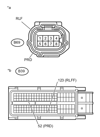
Text in Illustration *a Front view of wire harness connector
(to EDU)
*b Front view of wire harness connector
(to ECM)
Disconnect the EDU connector.
-
Disconnect the ECM connector.
-
Measure the resistance according to the value(s) in the table below.
Standard Resistance Tester Connection Condition Specified Condition B69-5 (PRD) - B39-52 (PRD) Always Below 1 Ω B69-1 (RLF) - B39-123 (RLFF) Always Below 1 Ω B69-5 (PRD) or B39-52 (PRD) - Body ground Always 10 kΩ or higher B69-1 (RLF) or B39-123 (RLFF) - Body ground Always 10 kΩ or higher -
Reconnect the EDU connector.
-
Reconnect the ECM connector.
NG
REPAIR OR REPLACE HARNESS OR CONNECTOR Click here
OK
-
-
INSPECT EDU (POWER SOURCE CIRCUIT)
-
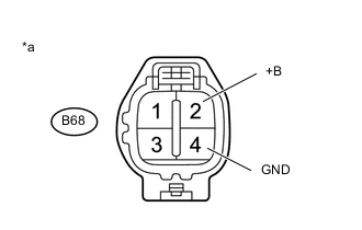
Text in Illustration *a Front view of wire harness connector
(to Injector Driver (EDU))
Disconnect the injector driver (EDU) connectors.
-
Measure the voltage according to the value(s) in the table below.
Standard Voltage Tester Connection Switch Condition Specified Condition B68-2 (+B) - B68-4 (GND) Ignition switch ON 11 to 14 V
NG
GO TO INJECTOR CIRCUIT Click here
OK
-
-
REPLACE EDU
-
Replace the EDU Click here.
NEXT
-
-
CHECK IF DTC OUTPUT RECURS (DTC P1271 AND/OR P1272)
-
Connect the intelligent tester to the DLC3.
-
Clear the DTCs Click here.
-
Turn the ignition switch off for 30 seconds or more.
-
Turn the ignition switch to ON.
-
Drive the vehicle at 50 km/h (31 mph) in 3rd gear, and then decelerate by completely releasing the accelerator pedal. Perform this 3 times.
-
Enter the following menus: Powertrain / Engine and ECT / DTC.
-
Read the pending DTCs.
Tech Tips
-
If no pending DTCs are output, proceed to the next step to check "All Readiness".
-
Perform the following procedure using the tester to determine whether or not the DTC judgment has been carried out.
-
Enter the following menus: Powertrain / Engine and ECT / Utility / All Readiness.
-
Input DTC P1271 and P1272.
-
Check the DTC judgment result.
Result Tester Display Result Proceed to Pending DTC P1271 and/or P1272 is output B All Readiness NORMAL A ABNORMAL B Tech Tips
If STATUS is INCOMPLETE or N/A, perform the following procedure 3 times: drive the vehicle at 50 km/h (31 mph) in 3rd gear, and then decelerate by completely releasing the accelerator pedal.
-
A
END
B
REPLACE ECM Click here
-
-
REPAIR OR REPLACE HARNESS OR CONNECTOR
-
Repair or replace the harness or connector.
NEXT
CONFIRM WHETHER MALFUNCTION HAS BEEN SUCCESSFULLY REPAIRED Click here
-
-
GO TO INJECTOR CIRCUIT
-
Go to injector circuit Click here.
NEXT
CONFIRM WHETHER MALFUNCTION HAS BEEN SUCCESSFULLY REPAIRED Click here
-
-
REPLACE ECM
-
Replace the ECM Click here.
NEXT
CONFIRM WHETHER MALFUNCTION HAS BEEN SUCCESSFULLY REPAIRED Click here
-
-
REPLACE COMMON RAIL ASSEMBLY
-
Replace the common rail assembly Click here.
NEXT
-
-
BLEED AIR FROM FUEL SYSTEM
-
Bleed the air from the fuel system Click here.
NEXT
-
-
CONFIRM WHETHER MALFUNCTION HAS BEEN SUCCESSFULLY REPAIRED
-
Connect the intelligent tester to the DLC3.
-
Clear the DTCs Click here.
-
Turn the ignition switch off for 30 seconds or more.
-
Turn the ignition switch to ON.
-
Drive the vehicle at 50 km/h (31 mph) in 3rd gear, and then decelerate by completely releasing the accelerator pedal. Perform this 3 times.
-
Enter the following menus: Powertrain / Engine and ECT / DTC.
-
Confirm that the pending DTC is not output again.
Tech Tips
Perform the following procedure using the tester to determine whether or not the DTC judgment has been carried out.
-
Enter the following menus: Powertrain / Engine and ECT / Utility / All Readiness.
-
Input DTC P1271 and P1272.
-
Check the DTC judgment result.
Tech Tips
If STATUS is INCOMPLETE or N/A, perform the following procedure 3 times: drive the vehicle at 50 km/h (31 mph) in 3rd gear, and then decelerate by completely releasing the accelerator pedal.
-
NEXT
END
-