ECD SYSTEM(w/o Gear Shift Indicator) FREEZE FRAME DATA
-
DESCRIPTION
-
The ECM records vehicle and driving condition information as freeze frame data the moment a DTC is stored. When troubleshooting, freeze frame data can be helpful in determining whether the vehicle was moving or stationary, whether the air fuel ratio was lean or rich, as well as the other data recorded at the time of a malfunction.
Tech Tips
If it is impossible to duplicate the problem even though a DTC is stored, confirm the freeze frame data.
-
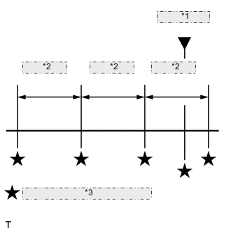
*1 DTC is stored *2 0.5 seconds *3 Freeze frame data recorded point The ECM records engine conditions in the form of freeze frame data every 0.5 seconds. Using an intelligent tester, 5 separate sets of freeze frame data can be checked.
-
3 data sets before the DTC was stored.
-
1 data set when the DTC was stored.
-
1 data set after the DTC was stored.
-
These data sets can be used to simulate the condition of the vehicle around the time of the occurrence of the malfunction. The data may assist in identifying the cause of the malfunction, and in judging whether it was temporary or not.
-
-
LIST OF FREEZE FRAME DATA
Tester Display Measurement Item Diagnostic Note Vehicle Speed Vehicle speed Speed indicated on speedometer Engine Speed Engine speed - Injection Volume Injection Volume - Calculate Load Calculated load Calculated load by ECM MAF Mass air flow volume If approximately 0.0 g/sec.:
-
Mass air flow meter power source circuit is open or shorted
-
VG circuit is open or shorted
If 200.0 g/sec. or more:
-
E2G circuit is open
Atmosphere Pressure Atmospheric pressure - MAP Absolute pressure inside intake manifold - Coolant Temp Engine coolant temperature If -40°C (-40°F), sensor circuit is open
If 140°C (284°F) or more, sensor circuit is shorted
Intake Air Intake air temperature If -40°C (-40°F), sensor circuit is open
If 140°C (284°F) or more, sensor circuit is shorted
Intake Air Temp (Turbo) Intake air temperature after intercooler If -40°C (-40°F), sensor circuit is open
If 190°C (374°F) or more, sensor circuit is shorted
Engine Run Time Accumulated engine running time - Initial Engine Coolant Temp Engine coolant temperature at engine start - Initial Intake Air Temp Intake air temperature at engine start - Battery Voltage Battery voltage - Pre Glow Pre-glow operation - After Glow After-glow operation - Accel Position Accelerator pedal position sensor - Accel Sens. No.1 Volt % Accelerator pedal position No. 1 output voltage - Accel Sens. No.2 Volt % Accelerator pedal position No. 2 output voltage - Target Throttle Position Target throttle position - Actual Throttle Position Actual throttle position - Diesel Throttle Learn Status Diesel throttle learn status - Throttle Sensor Volt % Throttle position sensor output voltage - Throttle Motor DUTY Throttle actuator - Injection Volume Injection volume - Inj. FB Vol. for Idle Injection feedback value for idle speed control - Inj Vol Feedback Learning Injection volume feedback learning value - Injection Feedback Val #1 Injection volume correction for cylinder 1 - Injection Feedback Val #2 Injection volume correction for cylinder 2 - Injection Feedback Val #3 Injection volume correction for cylinder 3 - Injection Feedback Val #4 Injection volume correction for cylinder 4 - Pilot 1 Injection Period Pilot 1 injection period - Pilot 2 Injection Period Pilot 2 injection period - Main Injection Period Main injection period - After Injection Period Post injection period - Pilot 1 Injection Timing Pilot 1 injection timing - Pilot 2 Injection Timing Pilot 2 injection timing - Main Injection Timing Main injection timing - After Injection Timing Post injection timing - Injector Memory Error EEPROM malfunction for injector - Reju Pilot Quantity Learning Pilot quantity learning prohibition - Pilot Quantity Learning Pilot quantity learning status - Fuel Press Fuel pressure - Fuel Temperature Fuel temperature - Target Pump SCV Current Pump current target final value - Pump SCV Learning Value Pump current learning value - Fuel Pressure Relief Valve Fuel pressure relief valve operation prohibition - AF Lambda B1S1 Lambda equivalent ratio - AFS Voltage B1S1 Air fuel ratio sensor output voltage Performing control the injection volume or control the injection volume for air fuel ratio sensor function of Active Test enables technician to check output voltage of sensor AFS Current B1S1 Air fuel ratio sensor output current - Target EGR Position Target EGR valve position - Actual EGR Valve Pos. Actual EGR valve position - EGR Close Lrn. Val. EGR valve fully closed position learned value - EGR Close Lrn. Status EGR valve fully closed position learning status - EGR Operation Prohibit EGR operation prohibition - Target Booster Pressure Target booster pressure - VN Turbo Command VN turbo command - Exhaust Temperature B1S1 Exhaust temperature sensor for B1S1 If 0°C (32°F), sensor circuit is open
If 1000°C (1832°F) or more, sensor circuit is shorted
Exhaust Temperature B1S2 Exhaust temperature sensor for B1S2 If 0°C (32°F), sensor circuit is open
If 1000°C (1832°F) or more, sensor circuit is shorted
DPF Differential Pressure DPF differential pressure - Catalyst Differential Press Standardized DPF differential pressure - Exhaust Fuel Addition FB Exhaust fuel addition correction value - DPF Thermal Deteriorate DPF thermal deterioration - DPF No Activate DPF operation - DPF PM Block DPF PM block - Catalyst Memory Error EEPROM malfunction for catalyst - Add. INJ Flow Insufficient Insufficient flow malfunction of exhaust addition injector - Add. INJ Flow Excessive Excessive flow malfunction of exhaust addition injector - DPF Over temperature Over temperature malfunction - Rich Spike Mal Malfunction of exhaust addition injector - Starter Signal Starter signal - Starter Control Starter control - Neutral Position SW Signal Neutral position switch signal - Clutch Switch Clutch switch - Reverse Switch - - Stop Light Switch Stop light switch - A/C Signal Air conditioning signal - Immobiliser Communication Immobiliser communication - Time after DTC Cleared Cumulative time after DTC cleared - Distance from DTC Cleared Accumulated distance after DTC cleared - Warmup Cycle Cleared DTC Warm-up cycle after DTC cleared - TC and TE1 TC and TE1 terminals of DLC3 - Engine Start Time - - Engine Speed (Starter Off) - - Starter Count - - Run Dist of Previous Trip - - Electric Duty Feedback Value - - A/C Duty Feedback Value - - PS Duty Feedback Value - - Idle Injection Volume (Min) - - Electric Fan Motor Electric fan motor - -