AUTOMATIC HIGH BEAM SYSTEM TERMINALS OF ECU
-
CHECK MAIN BODY ECU (INSTRUMENT PANEL JUNCTION BLOCK ASSEMBLY)
-
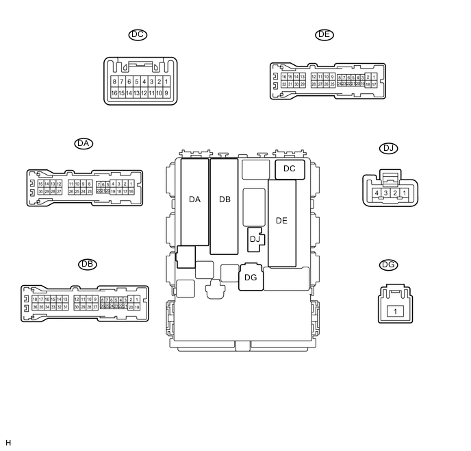
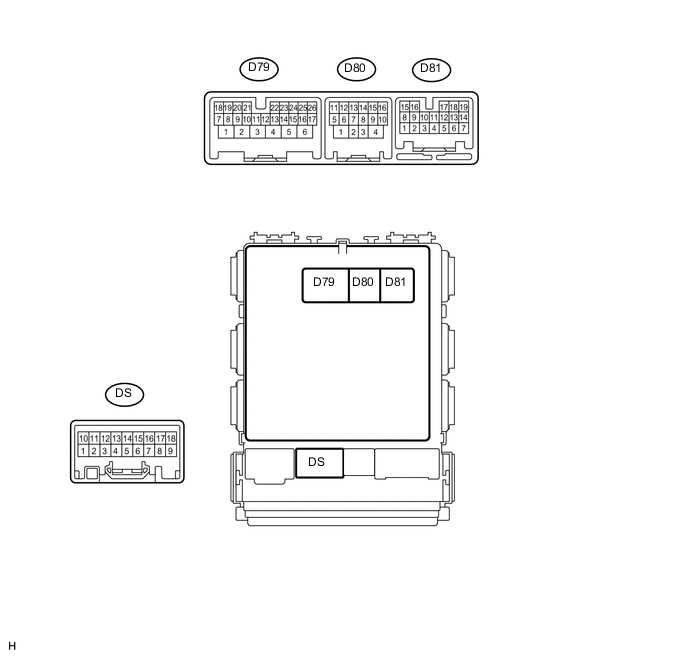
Disconnect the DB, DE and D80 main body ECU connectors.
-
Measure the voltage and resistance according to the value(s) in the table below.
Terminal No. (Symbol) Wiring Color Terminal Description Condition Specified Condition DB-12 (BECU) - Body ground W - Body ground Battery power supply Always 11 to 14 V DE-17 (GND1) - Body ground W-B - Body ground Body ground Always Below 1 Ω D80-4 (GND2) - Body ground W-B - Body ground Body ground Always Below 1 Ω -
Reconnect the DB, DE and D80 main body ECU connectors.
-
Measure the voltage and waveform according to the value(s) in the table below.
Terminal No. (Symbol) Wiring Color Terminal Description Condition Specified Condition D80-12 (DIM) - DE-17 (GND1) LG - W-B Dimmer relay drive output Dimmer switch in high or high flash position Below 1 V Dimmer switch not in high or high flash position 11 to 14 V D80-15 (CLTS) - DE-17 (GND1) V - W-B Rain sensor (automatic light control) signal input Ignition switch ON Below 1 V With the ignition switch ON and the light control switch in the AUTO position, cover the top of the rain sensor (automatic light control) with a lightproof object, and then expose the sensor Pulse generation (waveform varies depending on light volume) (Waveform 1) D81-18 (A) - DE-17 (GND1) V - W-B Light control switch AUTO position signal input Light control switch in AUTO position Below 1 V Light control switch not in AUTO position 11 to 14 V DJ-4 (HU) - DE-17 (GND1) P - W-B Dimmer switch high position signal input Dimmer switch in high or high flash position Below 1 V Dimmer switch in low position 11 to 14 V D81-15 (CANH) - Body ground R - Body ground CAN communication line Ignition switch ON Pulse generation D81-16 (CANL) - Body ground W - Body ground CAN communication line Ignition switch ON Pulse generation
-
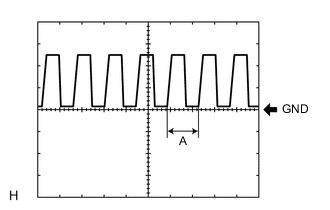
Waveform 1
Item Content Terminal No. (Symbol) D80-15 (CLTS) - DE-17 (GND1) Tool setting 5 V/DIV., 5 ms/DIV. Condition With the ignition switch ON and the light control switch in the AUTO position, cover the top of the rain sensor (automatic light control) with a lightproof object, and then expose the sensor Tech Tips
The brighter the surrounding area, the narrower width A becomes.
-
-
-
PRE-CRASH SAFETY CITY SENSOR Click here