LIGHTING SYSTEM Headlight Dimmer Switch Circuit
DESCRIPTION
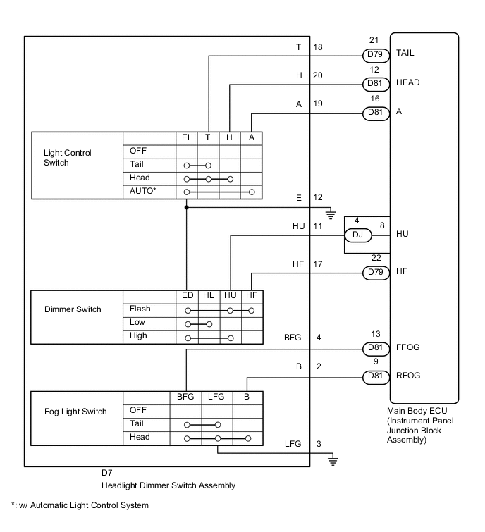
The main body ECU (instrument panel junction block assembly) receives light control switch signals, dimmer switch signal, fog light switch (front/rear) signals from the headlight dimmer switch assembly.
WIRING DIAGRAM
CAUTION / NOTICE / HINT
Note
-
As the door control battery is installed between the vehicle battery and main body ECU (instrument panel junction block assembly), first perform the inspections in On-Vehicle Inspection to confirm that there are no malfunctions in the power source circuit for the main body ECU (instrument panel junction block assembly) before performing this troubleshooting procedure.
PROCEDURE
-
READ VALUE USING GTS (HEADLIGHT DIMMER SWITCH)
-
Using the GTS, read the Data List Click here.
Main Body Tester Display Measurement Item/Range Normal Condition Diagnostic Note Dimmer SW Dimmer switch signal / ON or OFF ON: Dimmer switch on
OFF: Dimmer switch off
- Passing Light SW Passing light switch signal / ON or OFF ON: Passing light switch on
OFF: Passing light switch off
- Front Fog Light SW Front fog light switch signal / ON or OFF ON: Front fog light switch on
OFF: Front fog light switch off
w/ Front Fog Light Rear Fog Light SW Rear fog light switch signal / ON or OFF ON: Rear fog light switch on
OFF: Rear fog light switch off
w/ Rear Fog Light Auto Light SW Auto light switch signal / ON or OFF ON: Auto light switch on
OFF: Auto light switch off
w/ Automatic Light Control System Head Light SW (Head) Headlight switch signal / ON or OFF ON: Headlight switch on
OFF: Headlight switch off
- Head Light SW (Tail) Taillight switch signal / ON or OFF ON: Taillight switch on
OFF: Taillight switch off
-
OK 
PROCEED TO NEXT SUSPECTED AREA SHOWN IN PROBLEM SYMPTOMS TABLE Click here
NG 
-
-
INSPECT HEADLIGHT DIMMER SWITCH ASSEMBLY (TURN SIGNAL SWITCH)
-
Remove the headlight dimmer switch assembly Click here.
-
Inspect the headlight dimmer switch assembly Click here.
NG
PROCEED TO NEXT SUSPECTED AREA SHOWN IN PROBLEM SYMPTOMS TABLE Click here
OK
-
-
CHECK HARNESS AND CONNECTOR (HEADLIGHT DIMMER SWITCH ASSEMBLY - MAIN BODY ECU AND BODY GROUND)
-
Disconnect the D7 headlight dimmer switch assembly connector.
-
Disconnect the D79, D81 and DJ main body ECU (instrument panel junction block assembly) connectors.
-
Measure the resistance according to the value(s) in the table below.
Standard Resistance Tester Connection Condition Specified Condition D7-18 (T) - D79-21 (TAIL) Always Below 1 Ω D7-20 (H) - D81-12 (HEAD) Always Below 1 Ω D7-19 (A) - D81-16 (A) Always Below 1 Ω D7-11 (HU) - DJ-4 (HU) Always Below 1 Ω D7-17 (HF) - D79-22 (HF) Always Below 1 Ω D7-4 (BFG) - D81-13 (FFOG) Always Below 1 Ω D7-2 (B) - D79-9 (RFOG) Always Below 1 Ω D7-18 (T) - Body ground Always 10 kΩ or higher D7-20 (H) - Body ground Always 10 kΩ or higher D7-19 (A) - Body ground Always 10 kΩ or higher D7-11 (HU) - Body ground Always 10 kΩ or higher D7-17 (HF) - Body ground Always 10 kΩ or higher D7-4 (BFG) - Body ground Always 10 kΩ or higher D7-2 (B) - Body ground Always 10 kΩ or higher D7-3 (LFG) - Body ground Always Below 1 Ω
OK
REPLACE MAIN BODY ECU (INSTRUMENT PANEL JUNCTION BLOCK ASSEMBLY)
NG
REPAIR OR REPLACE HARNESS OR CONNECTOR
-