LIGHTING SYSTEM TERMINALS OF ECU

-
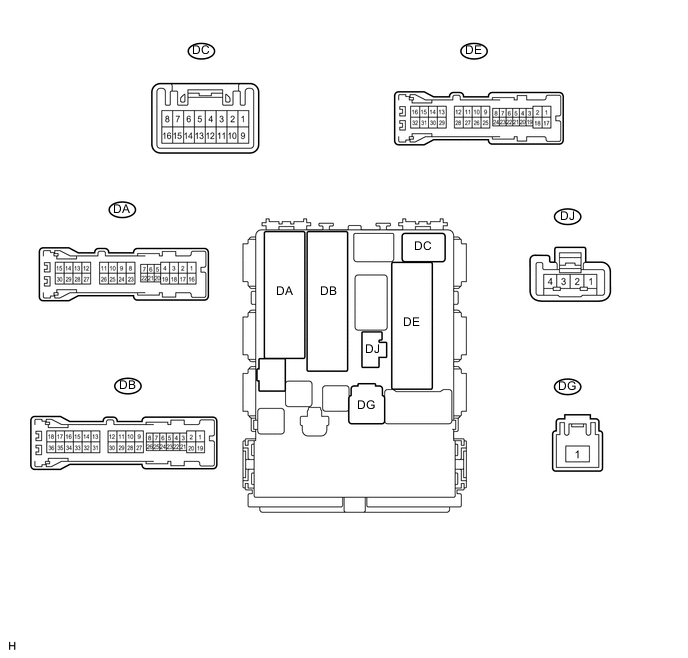
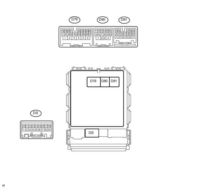
CHECK MAIN BODY ECU (INSTRUMENT PANEL JUNCTION BLOCK ASSEMBLY)
-
Disconnect the DB, DE and D80 main body ECU connectors.
-
Measure the voltage and resistance according to the value(s) in the table below.
Terminal No. (Symbol) Wiring Color Terminal Description Condition Specified Condition DB-12 (BECU) - Body ground W - Body ground Battery power supply Always 11 to 14 V DE-17 (GND1) - Body ground W-B - Body ground Ground Always Below 1 Ω D80-4 (GND2) - Body ground W-B - Body ground Ground Always Below 1 Ω -
Reconnect the DB, DE and D80 main body ECU connectors.
-
Measure the voltage and pulse according to the value(s) in the table below.
Terminal No. (Symbol) Wiring Color Terminal Description Condition Specified Condition D79-20 (HRLY) -DE-17 (GND1) B - W-B H-LP relay drive output Light control switch in head position Below 1 V Light control switch not in head position 11 to 14 V DG-1 (TRLY) -DE-17 (GND1) W - W-B Taillight relay drive output Light control switch in tail position Below 1 V Light control switch not in tail position 11 to 14 V DB-33 (TRLY) - DE-17 (GND1) LG - W-B Front parking light LH signal output Light control switch in tail position 11 to 14 V Light control switch not in tail position Below 1 V DB-15 (TRLY) - DE-17 (GND1) G - W-B Front parking light RH signal output Light control switch in tail position 11 to 14 V Light control switch not in tail position Below 1 V DA-29 (TRLY) - DE-17 (GND1) G - W-B Rear taillight signal output Light control switch in tail position 11 to 14 V Light control switch not in tail position Below 1 V D80-12 (DIM) - DE-17 (GND1) LG - W-B Dimmer relay drive output Dimmer switch in high or high flash position Below 1 V Dimmer switch not in high or high flash position 11 to 14 V D79-3 (DRLE) - DE-17 (GND1)*1 W - W-B DRL relay drive output Daytime running light on 11 to 14 V Daytime running light off Below 1 V D79-21 (TAIL) - DE-17 (GND1) W - W-B Light control switch tail position signal input Light control switch in tail or head position Below 1 V Light control switch in neither tail nor head position 11 to 14 V D81-12 (HEAD) - DE-17 (GND1) L - W-B Light control switch head position input Light control switch in head position Below 1 V Light control switch not in head position 11 to 14 V DJ-4 (HU) - DE-17 (GND1) P - W-B Dimmer switch high position signal input Dimmer switch in high or high flash position Below 1 V Dimmer switch in low position 11 to 14 V D79-22 (HF) - DE-17 (GND1) R - W-B Dimmer switch high flash position signal input Dimmer switch in high flash position Below 1 V Dimmer switch not in high flash position 11 to 14 V D81-13 (FFOG) - DE-17 (GND1)*2 P - W-B Front fog light switch input Front fog light switch on Below 1 V Front fog light switch off 11 to 14 V D81-14 (DRLE) - DE-17 (GND1)*3 W - W-B DRL relay drive output Daytime running light on 11 to 14 V Daytime running light off Below 1 V D81-9 (RFOG) - DE-17 (GND1)*4 SB - W-B Rear fog light switch input Rear fog light switch on Below 1 V Rear fog light switch off 11 to 14 V D81-18 (A) - DE-17 (GND1)*5 V - W-B Light control switch AUTO position signal input Light control switch in AUTO position Below 1 V Light control switch not in AUTO position 11 to 14 V D81-17 (FFGO) - DE-17 (GND1)*2 G - W-B Front fog light relay drive output Light control switch in head position and front fog light switch on Below 1 V Front fog light switch off 11 to 14 V D80-11 (RFGO) - DE-17 (GND1)*4 GR - W-B Rear fog light relay drive output Light control switch in head position and rear fog light switch on Below 1 V Rear fog light switch off 11 to 14 V D80-15 (CLTS) - DE-17 (GND1)*5 V - W-B Rain sensor (automatic light control) signal input Ignition switch off Below 1 V Automatic light control system operates Pulse generation
(See waveform 1)
D79-8 (LCTY) - DE-17 (GND1) SB - W-B Courtesy switch input
(Rear left door circuit)
Rear door LH open Below 1 V Rear door LH closed 11 to 14 V DA-21 (DCTY) - DE-17 (GND1)*6
DC-6 (DCTY) - DE-17 (GND1)*7
W - W-B*6
SB - W-B*7
Courtesy switch input
(Driver side door circuit)
Driver side door open Below 1 V Driver side door closed 11 to 14 V DE-19 (RCTY) - DE-17 (GND1) LG - W-B Courtesy switch input
(Rear right door circuit)
Rear door RH open Below 1 V Rear door RH closed 11 to 14 V DE-20 (PCTY) - DE-17 (GND1)*6
DA-24 (PCTY) - DE-17 (GND1)*7
Y - W-B*6
W - W-B*7
Courtesy switch input
(Front passenger side door circuit)
Front passenger side door open Below 1 V Front passenger side door closed 11 to 14 V DA-7 (LGCY) - DE-17 (GND1)*8 LG - W-B Courtesy switch input Luggage compartment door open Below 1 V Luggage compartment door closed 11 to 14 V DA-7 (BCTY) - DE-17 (GND1)*9 LG - W-B Courtesy switch input Back door open Below 1 V Back door closed 11 to 14 V D79-25 (LSWD) - DE-17 (GND1) GR - W-B Driver side door unlock detection switch input Driver side door locked Below 1 V Driver side door unlocked 11 to 14 V
-
*1: for LHD (w/o Foot Light) and RHD (w/o Theft Deterrent System)
-
*2: w/ Front Fog Light
-
*3: for all except LHD (w/o Foot Light) and RHD (w/o Theft Deterrent System)
-
*4: w/ Rear Fog Light
-
*5: w/ Automatic Light Control System
-
*6: for LHD
-
*7: for RHD
-
*8: for Sedan
-
*9: for Wagon
-
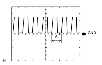
Waveform 1
Item Content Terminal No. (Symbol) D80-15 (CLTS) - DE-17 (GND1) Tool setting 5 V/DIV., 5 ms./DIV. Condition Ignition switch ON
Headlight dimmer switch AUTO
Cover the rain sensor with a hand → Expose the rain sensor to the ambient light
Tech Tips
If the ambient light becomes brighter, width A becomes narrower.
-
-
-
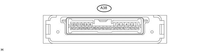
CHECK HEADLIGHT SWIVEL ECU ASSEMBLY (w/ AFS)
-
Disconnect the A38 headlight swivel ECU connector.
-
Measure the voltage and resistance according to the value(s) in the table below.
Terminal No. (Symbol) Wiring Color Terminal Description Condition Specified Condition A38-14 (IGS) - Body ground P - Body ground Ignition power supply Ignition switch ON 11 to 14 V Ignition switch off Below 1 V A38-15 (IG) - Body ground P - Body ground Ignition power supply Ignition switch ON 11 to 14 V Ignition switch off Below 1 V A38-22 (E1) - Body ground W-B - Body ground Ground Always Below 1 Ω -
Reconnect the A38 headlight swivel ECU connector.
-
Measure the voltage, resistance and pulse according to the value(s) in the table below.
Terminal No. (Symbol) Wiring Color Terminal Description Condition Specified Condition A38-1 (SMBL) - A38-22 (E1) W - W-B Swivel motor LH power output Ignition switch ON 11 to 14 V A38-2 (SMBR) - A38-22 (E1) GR - W-B Swivel motor RH power output Ignition switch ON 11 to 14 V A38-3 (RSW)* - A38-22 (E1) R - W-B Back-up light switch signal input Ignition switch ON
Shift lever in R
11 to 14 V A38-10 (SMR) - A38-22 (E1) R - W-B Swivel motor RH Ignition switch ON Pulse generation A38-11 (RH+) - A38-22 (E1) L - W-B Headlight leveling motor RH Ignition switch ON Pulse generation A38-18 (SBR) - A38-22 (E1) Y - W-B Vehicle height signal Ignition switch ON 5 V A38-19 (SHRL) - A38-22 (E1) GR - W-B Vehicle height signal Ignition switch ON (no passengers, no luggage, vehicle not moving) 2.5 V A38-21 (SGR) - A38-22 (E1) B - W-B Vehicle height signal Always Below 1 Ω A38-27 (LH-) - A38-22 (E1) LG - W-B Headlight leveling motor LH Always Below 1 Ω A38-28 (RH-) - A38-22 (E1) B - W-B Headlight leveling motor RH Always Below 1 Ω A38-29 (SML) - A38-22 (E1) Y-B - W-B Swivel motor LH Ignition switch ON Pulse generation A38-30 (LH+) - A38-22 (E1) G - W-B Headlight leveling motor LH Ignition switch ON Pulse generation A38-32 (MSW) - A38-22 (E1) V - W-B Headlight swivel main switch signal input Ignition switch ON
Headlight swivel main switch on
Below 1 V Ignition switch ON
Headlight swivel main switch off
11 to 14 V A38-12 (CANH) - A38-22 (E1) P - W-B CAN communication Ignition switch ON Pulse generation A38-13 (CANL) - A38-22 (E1) W - W-B CAN communication Ignition switch ON Pulse generation *: for Manual Transaxle
-
-
CHECK HEADLIGHT LEVELING ECU ASSEMBLY (w/o AFS)

-
Disconnect the A66 headlight leveling ECU connector.
-
Measure the voltage and resistance according to the value(s) in the table below.
Terminal No. (Symbol) Wiring Color Terminal Description Condition Specified Condition A66-1 (IG) - Body ground P - Body ground Ignition power supply Ignition switch ON 11 to 14 V Ignition switch off Below 1 V A66-9 (E1) - Body ground W-B - Body ground Ground Always Below 1 Ω -
Reconnect the A66 headlight leveling ECU connector.
-
Measure the voltage, resistance and pulse according to the value(s) in the table below.
Terminal No. (Symbol) Wiring Color Terminal Description Condition Specified Condition A66-4 (RSW)* - A66-9 (E1) R - W-B Back-up light switch signal input Ignition switch ON
Shift lever in R
11 to 14 V A66-6 (CANH) - A66-9 (E1) P - W-B CAN communication Ignition switch ON Pulse generation A66-7 (CANL) - A66-9 (E1) W - W-B CAN communication Ignition switch ON Pulse generation A66-10 (RH+) - A66-9 (E1) L - W-B Headlight leveling motor RH power supply Ignition switch off Below 1 V Ignition switch ON 11 to 14 V A66-11 (LH+) - A66-9 (E1) G - W-B Headlight leveling motor LH power supply Ignition switch off Below 1 V Ignition switch ON 11 to 14 V A66-12 (SBR) - A66-9 (E1) Y - W-B Rear height control sensor power supply Ignition switch off Below 1 V Ignition switch ON 4.75 to 5.25 V A66-17 (RHT) - A66-9 (E1) P - W-B Headlight leveling motor RH operation signal input With low beam headlights on, vehicle height not changed Below 1 V With low beam headlights on, vehicle height changed and maintained for more than 3 seconds 1 to 14.4 V A66-18 (LHT) - A66-9 (E1) B - W-B Headlight leveling motor LH operation signal input With low beam headlights on, vehicle height not changed Below 1 V With low beam headlights on, vehicle height changed and maintained for more than 3 seconds 1 to 14.4 V A66-19 (SHRL) - A66-21 (SGR) GR - B Rear height control sensor signal input Ignition switch ON
(no passengers, no luggage, vehicle not moving)
Approximately 2.5 V (Vehicle is level)
(The value decreases as the front of the vehicle is raised.)
A66-21 (SGR) - A66-9 (E1) B - W-B Rear height control sensor ground Always Below 1 Ω A66-23 (RH-) - A66-9 (E1) B - W-B Headlight leveling motor RH ground Always Below 1 Ω A66-24 (LH-) - A66-9 (E1) LG - W-B Headlight leveling motor LH ground Always Below 1 Ω *: for Manual Transaxle
-
-
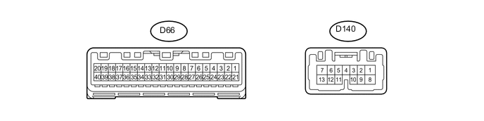
CHECK COMBINATION METER ASSEMBLY
-
Disconnect the D66 and D140 combination meter connectors.
-
Measure the voltage and resistance according to the value(s) in the table below.
Terminal No. (Symbol) Wiring Color Terminal Description Condition Specified Condition D66-39 (IG+) - Body ground P - Body ground Ignition power supply Ignition switch ON 11 to 14 V Ignition switch off Below 1 V D66-40 (B) - Body ground W - Body ground Battery Always 11 to 14 V D140-1 (B) - Body ground P - Body ground Battery Always 11 to 14 V D140-3 (HAZ) - Body ground GR - Body ground Hazard warning signal switch signal (Output) Ignition switch ON, hazard warning signal switch on 11 to 14 V Ignition switch ON, hazard warning signal switch off Below 1 V D66-21 (ET) - Body ground W-B - Body ground Ground Always Below 1 Ω -
Reconnect the D66 and D140 combination meter connectors.
-
Measure the voltage according to the value(s) in the table below.
Terminal No. (Symbol) Wiring Color Terminal Description Condition Specified Condition D140-6 (SW) - Body ground L - Body ground Turn signal switch (full turn) signal Headlight dimmer switch on (full turn) Below 1 V Headlight dimmer switch off 11 to 14 V D140-7 (LR) - Body ground L - Body ground RH turn indicator light signal (Output) Ignition switch ON, RH turn indicator light off Below 1 V Ignition switch ON, RH turn indicator light blinking 11 to 14 V ←→ Below 1 V D140-9 (ER) - Body ground G - Body ground RH turn indicator light signal (Input) Ignition switch ON, RH turn signal switch on Below 1 V Ignition switch ON, RH turn signal switch off 11 to 14 V D140-10 (EL) - Body ground G - Body ground LH turn indicator light signal (Input) Ignition switch ON, LH turn signal switch on Below 1 V Ignition switch ON, LH turn signal switch off 11 to 14 V D140-13 (LL) - Body ground Y - Body ground LH turn indicator light signal (Output) Ignition switch ON, LH turn indicator light off Below 1 V Ignition switch ON, LH turn indicator light blinking 11 to 14 V ←→ Below 1 V
-