LUGGAGE COMPARTMENT DOOR OPENER SYSTEM TERMINALS OF ECU
-
CHECK MAIN BODY ECU (INSTRUMENT PANEL JUNCTION BLOCK)
-
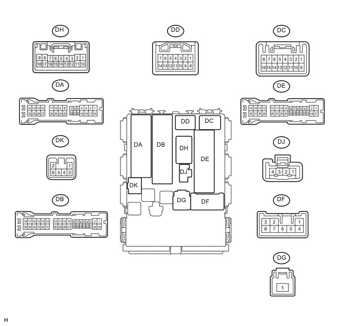
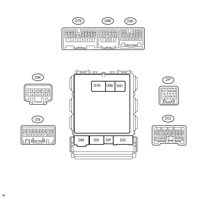
Disconnect the DB, DE, DF and D80 ECU connectors.
-
Measure the voltage and resistance according to the value(s) in the table below.
Terminal No. (Symbol) Wiring Color Terminal Description Condition Specified Condition DB-30 (BECU) - Body ground W - Body ground ECU power supply (from battery) Always 11 to 14 V DF-3 (IG) - Body ground W - Body ground IG signal circuit Ignition switch off Below 1 V Ignition switch ON 11 to 14 V DF-5 (ACC) - Body ground W - Body ground ACC signal circuit Ignition switch off Below 1 V Ignition switch ACC 11 to 14 V DE-17 (GND1) - Body ground W-B - Body ground Ground circuit Always Below 1 Ω D80-4 (GND2) - Body ground W-B - Body ground Ground circuit Always Below 1 Ω If the result is not as specified, there may be a malfunction on the wire harness side.
-
Reconnect the DB, DE, DF and D80 ECU connectors.
-
Measure the voltage according to the value(s) in the table below.
Terminal No. (Symbol) Wiring Color Terminal Description Condition Specified Condition D79-1 (TR+) - Body ground R - Body ground Luggage compartment door lock motor drive output Back door opener switch off Below 1 V Back door opener switch on 11 to 14 V D79-12 (BDSU) - Body ground V - Body ground Back door opener switch input Back door opener switch off 11 to 14 V Back door opener switch on Below 1 V
-