LOWER INSTRUMENT PANEL INSTALLATION
CAUTION / NOTICE / HINT
Tech Tips
-
Use the same procedure for RHD and LHD vehicles.
-
The procedure listed below is for LHD vehicles.
-
A bolt without a torque specification is shown in the standard bolt chart Click here.
PROCEDURE
-
INSTALL LOWER INSTRUMENT PANEL SUB-ASSEMBLY
-
Cut off both ends at the positions shown in the illustration (runner) (when installing new part).
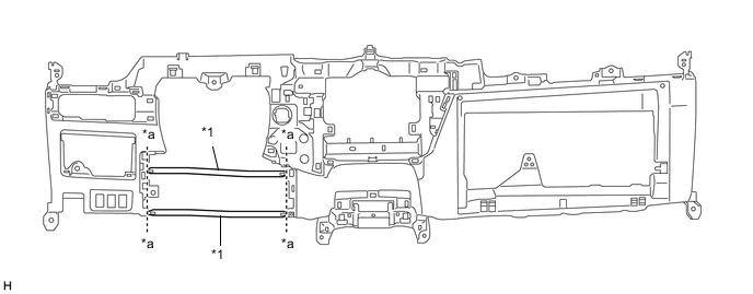
Text in Illustration *1 Runner - - *a Cut-off Line - - -
Attach the 2 guides to install the lower instrument panel sub-assembly.
-
for Automatic Air Conditioning System:
Connect the cooler (room temperature sensor) thermistor.
-
Attach the clamps.
-
Install the 2 screws.
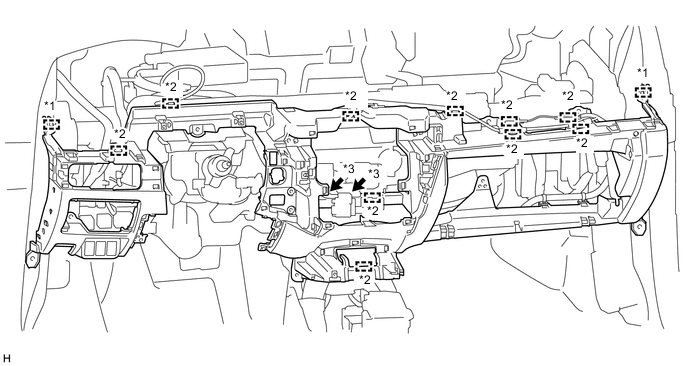
Text in Illustration *1 Guide *2 Clamp *3 Screw - - -
Install the 9 screws <C>, 2 bolts <D> and screw <E>.
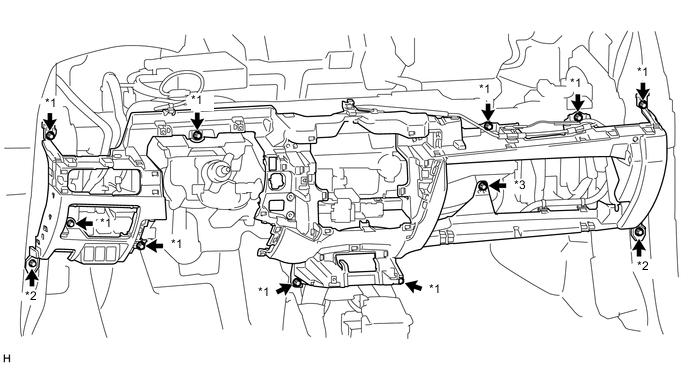
Text in Illustration *1 Screw <C> *2 Bolt <D> *3 Screw <E> - -
-
-
INSTALL HOOD LOCK CONTROL LEVER SUB-ASSEMBLY
-
INSTALL ELECTRIC PARKING BRAKE SWITCH ASSEMBLY
-
INSTALL COWL SIDE TRIM BOARD LH
-
INSTALL COWL SIDE TRIM BOARD RH
-
INSTALL FRONT DOOR SCUFF PLATE LH
-
INSTALL FRONT DOOR SCUFF PLATE RH
-
INSTALL NO. 2 HEATER TO REGISTER DUCT
-
Attach the guide to install the No. 2 heater to register duct.
-
-
INSTALL DEFROSTER NOZZLE ASSEMBLY
-
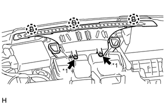
Text in Illustration *1 Clip <B> Attach the 3 claws to install the defroster nozzle assembly.
-
Install the 2 clips <B>.
-
-
INSTALL STEREO OPENING COVER WITH AIR CONDITIONING CONTROL ASSEMBLY (w/o Audio)
-
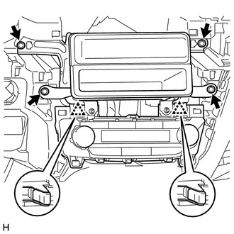
Connect the connector.
-
Attach the 2 clips to install the stereo opening cover with air conditioning control assembly.
-
Install the 4 screws.
-
-
INSTALL RADIO RECEIVER ASSEMBLY WITH AIR CONDITIONING CONTROL ASSEMBLY (w/ Audio, for Radio Receiver Type)
-
INSTALL RADIO AND DISPLAY RECEIVER ASSEMBLY WITH AIR CONDITIONING CONTROL ASSEMBLY (w/ Audio, for Radio and Display Type)
-
INSTALL COIN BOX ASSEMBLY
-
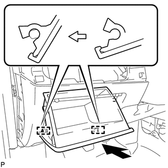
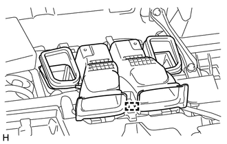
Attach the 2 hinges to install the coin box assembly.
-
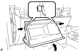
While pushing in the sides of the coin box as indicated by the arrows in the illustration, close the coin box assembly to engage the 2 stoppers.
-
-
INSTALL LOWER NO. 1 INSTRUMENT PANEL AIRBAG ASSEMBLY
-
INSTALL NO. 1 INSTRUMENT PANEL UNDER COVER SUB-ASSEMBLY
-
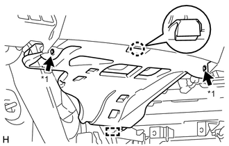
Text in Illustration *1 Screw <A> Connect the connector.
-
Attach the guide and claw to install the No. 1 instrument panel under cover sub-assembly.
-
Install the 2 screws <A>.
-
-
INSTALL NO. 2 INSTRUMENT PANEL UNDER COVER SUB-ASSEMBLY
-
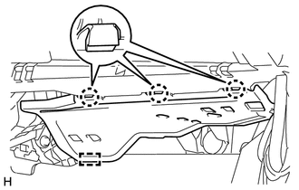
Connect the connector.
-
Attach the guide and 3 claws to install the No. 2 instrument panel under cover sub-assembly.
-
-
INSTALL NO. 1 SWITCH HOLE BASE
-
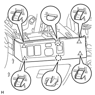
for LHD:
-
Connect the connectors.
-
Attach the 4 clips and 2 claws to install the No. 1 switch hole base.
-
-
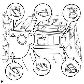
for RHD:
-
Connect the connectors.
-
Attach the 4 clips and 2 claws to install the No. 1 switch hole base.
-
-
-
INSTALL HEADLIGHT DIMMER SWITCH ASSEMBLY
-
INSTALL CONSOLE BOX ASSEMBLY
-
INSTALL UPPER INSTRUMENT PANEL SUB-ASSEMBLY
-
CONNECT CABLE TO NEGATIVE BATTERY TERMINAL
Note
When disconnecting the cable, some systems need to be initialized after the cable is reconnected Click here.
-
CHECK SRS WARNING LIGHT