UPPER INSTRUMENT PANEL INSTALLATION
CAUTION / NOTICE / HINT
Tech Tips
-
Use the same procedure for RHD and LHD vehicles.
-
The procedure listed below is for LHD vehicles.
PROCEDURE
-
INSTALL UPPER INSTRUMENT PANEL SUB-ASSEMBLY
-
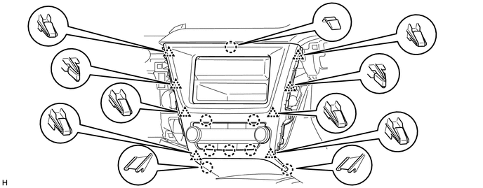
for 10 Speakers:
Connect the connectors.
-
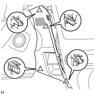
Attach the 5 guides and 7 clips to install the upper instrument panel sub-assembly.
-
Install the passenger airbag installation bolt <B>.
- Torque:
- 20 N*m { 204 kgf*cm, 15 ft.*lbf }
-
Install the 2 screws <A>.
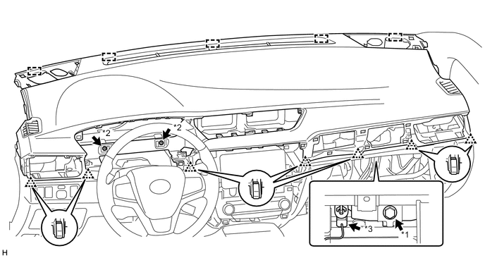
Text in Illustration *1 Passenger Airbag Installation Bolt <B> *2 Screw <A> *3 Passenger Airbag Connector - - -
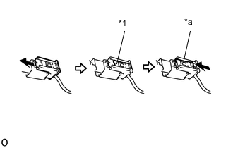
Text in Illustration *1 Lock Slider *a Lock Position Connect the passenger airbag connector.
Note
When handling the passenger airbag connector, take care not to damage the airbag wire harness.
-
Check that the lock slider is in the lock position.
-
-
INSTALL NO. 2 INSTRUMENT PANEL SPEAKER PANEL SUB-ASSEMBLY
-
for 6 Speakers:
Connect the connector.
-
Attach the 2 guides, 2 clips and claw to install the No. 2 instrument panel speaker panel sub-assembly.
-
-
INSTALL NO. 1 INSTRUMENT PANEL SPEAKER PANEL SUB-ASSEMBLY
-
for 6 Speakers:
Connect the connector.
-
Attach the 2 guides, 2 clips and claw to install the No. 1 instrument panel speaker panel sub-assembly.
-
-
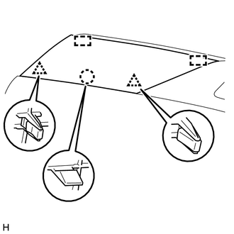
INSTALL FRONT PILLAR GARNISH LH
-
for Sedan:
-
for Wagon:
-
-
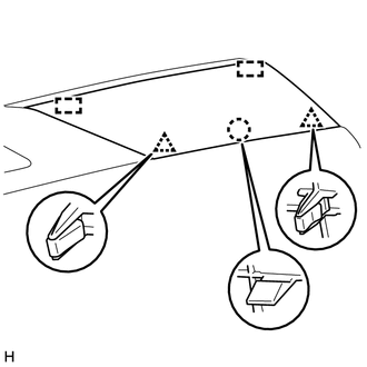
INSTALL FRONT PILLAR GARNISH RH
-
for Sedan:
-
for Wagon:
-
-
CONNECT FRONT DOOR OPENING TRIM WEATHERSTRIP LH
-
Connect the front door opening trim weatherstrip LH.
-
-
CONNECT FRONT DOOR OPENING TRIM WEATHERSTRIP RH
-
Connect the front door opening trim weatherstrip RH.
-
-
INSTALL GLOVE COMPARTMENT DOOR ASSEMBLY
-
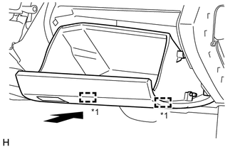
Text in Illustration *1 Hinge Attach the 2 hinges to install the glove compartment door assembly.
Note
When installing the glove compartment door assembly, make sure to install horizontally. Installing the glove compartment door assembly from above causes the hinges to become loose.
-
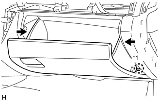
Text in Illustration *1 Glove Compartment Door Damper While pushing in the sides of the glove compartment door assembly, attach the 2 stoppers.
-
Attach the claw to connect the glove compartment door damper.
-
-
INSTALL INSTRUMENT SIDE PANEL LH
-
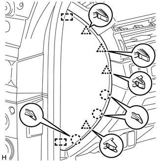
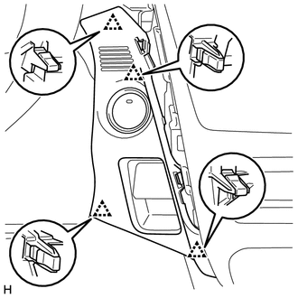
Attach the 2 guides, 4 clips and 3 claws to install the instrument side panel LH.
-
-
INSTALL INSTRUMENT SIDE PANEL RH
-
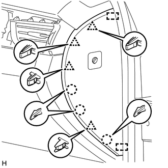
Connect the connector.
-
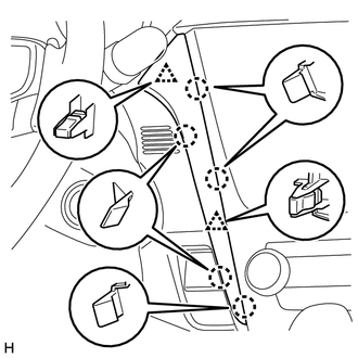
Attach the 2 guides, 4 clips and 3 claws to install the instrument side panel RH.
-
-
INSTALL CENTER INSTRUMENT CLUSTER FINISH PANEL SUB-ASSEMBLY
-
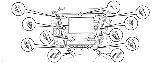
w/o Audio, for Radio Receiver Type:
-
Attach the 8 claws and 8 clips to install the center instrument cluster finish panel sub-assembly.
-
-
for Radio and Display Type:
-
Attach the 8 claws and 8 clips to install the center instrument cluster finish panel sub-assembly.
-
-
-
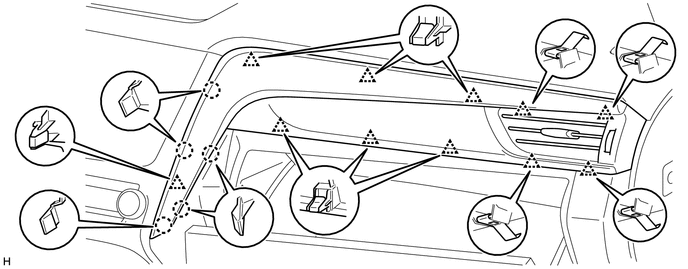
INSTALL INSTRUMENT PANEL FINISH PANEL END RH
-
Attach the 5 claws and 11 clips to install the instrument panel finish panel end RH together with the No. 1 instrument panel register assembly.
-
-
INSTALL COMBINATION METER ASSEMBLY
-
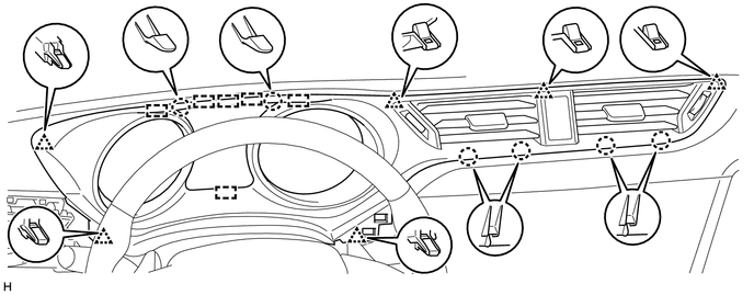
INSTALL CENTER INSTRUMENT PANEL REGISTER ASSEMBLY
-
Connect the connector.
-
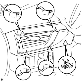
Attach the 6 guides, 6 claws and 6 clips to install the center instrument panel register assembly.
-
-
INSTALL LOWER CENTER INSTRUMENT PANEL FINISH PANEL
-
w/o Entry and Start System:
-
Attach the 4 clips to install the lower center instrument panel finish panel.
-
-
w/ Entry and Start System:
-
Connect the connector.
-
Attach the 4 clips to install the lower center instrument panel finish panel.
-
-
-
INSTALL NO. 2 INSTRUMENT CLUSTER FINISH PANEL GARNISH
-
Attach the 5 claws and 2 clips to install the No. 2 instrument cluster finish panel garnish.
-
-
INSTALL INSTRUMENT PANEL FINISH PANEL END LH
-
Attach the 5 clips and to install the instrument panel finish panel end LH together with the No. 2 instrument panel register assembly.
-
-
CONNECT CABLE TO NEGATIVE BATTERY TERMINAL
Note
When disconnecting the cable, some systems need to be initialized after the cable is reconnected Click here.
-
CHECK SRS WARNING LIGHT