CONDENSER INSTALLATION
PROCEDURE
-
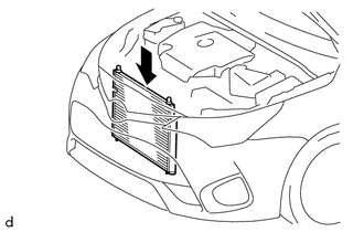
INSTALL CONDENSER ASSEMBLY WITH RECEIVER
-
Install the condenser assembly with receiver as shown in the illustration.
Tech Tips
If the condenser is replaced with a new one, add compressor oil to the new condenser.
Capacity 40 cc (1.4 fl.oz) for HFC-134a(R134a): Compressor oil ND-OIL 8 or equivalent for HFO-1234yf(R1234yf): Compressor oil ND-OIL 12 or equivalent
-
-
CONNECT SUCTION PIPE SUB-ASSEMBLY
-
Remove the attached vinyl tape from the pipe and the connecting part of the cooler condenser assembly.
-
Sufficiently apply compressor oil to a new O-ring and the fitting surface of the pipe joint.
for HFC-134a(R134a): Compressor oil ND-OIL 8 or equivalent for HFO-1234yf(R1234yf): Compressor oil ND-OIL 12 or equivalent -
Install the O-ring to the suction pipe sub-assembly.
-
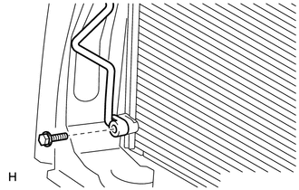
Install the suction pipe sub-assembly to the cooler condenser assembly with the bolt.
- Torque:
- 5.4 N*m { 55 kgf*cm, 48 in.*lbf }
-
-
CONNECT DISCHARGE HOSE SUB-ASSEMBLY
-
Remove the attached vinyl tape from the hose and the connecting part of the cooler condenser assembly.
-
Sufficiently apply compressor oil to a new O-ring and the fitting surface of the hose joint.
for HFC-134a(R134a): Compressor oil ND-OIL 8 or equivalent for HFO-1234yf(R1234yf): Compressor oil ND-OIL 12 or equivalent -
Install the O-ring to the discharge hose sub-assembly.
-
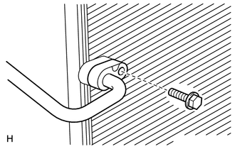
Install the discharge hose sub-assembly to the cooler condenser assembly with the bolt.
- Torque:
- 5.4 N*m { 55 kgf*cm, 48 in.*lbf }
-
-
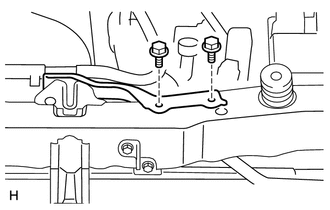
INSTALL NO. 2 FAN SHROUD
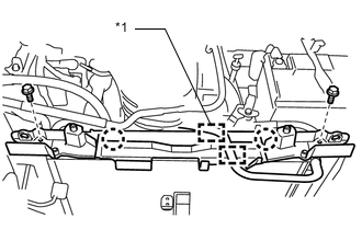
Text in Illustration *1 for Automatic Transaxle, CVT
-
Attach the 2 claws to install the fan shroud.
-
Install the 2 bolts.
- Torque:
- 7.0 N*m { 71 kgf*cm, 62 in.*lbf }
-
for Automatic Transaxle, CVT:
Attach the clamps to install the No. 3 water by-pass hose.
-
for Manual Transaxle:
Attach the clamp to install the No. 3 water by-pass hose.
-
-
INSTALL RADIATOR SUPPORT CUSHION
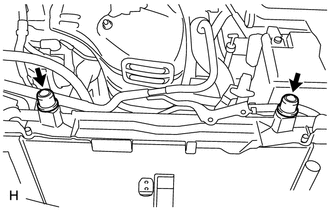
-
Install the 2 cushions.
-
-
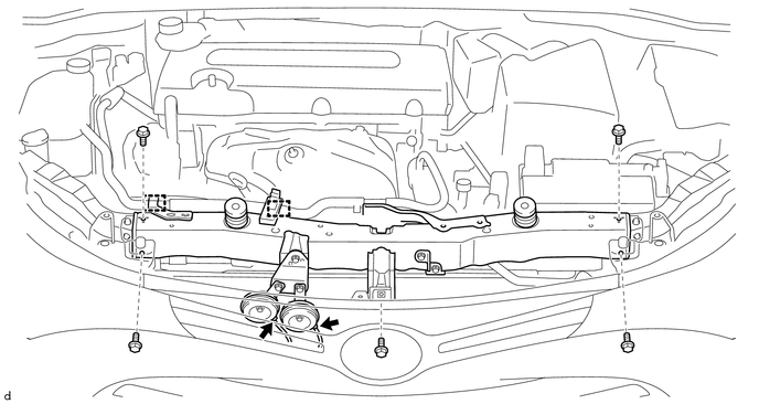
INSTALL UPPER RADIATOR SUPPORT
-
Install the radiator support upper with the 5 bolts.
- Torque:
- 13 N*m { 133 kgf*cm, 9 ft.*lbf }
-
Attach the 2 clamps to install the No. 2 water by-pass hose.
-
Connect the 2 horn connectors.
-
-
INSTALL HOOD LOCK ASSEMBLY
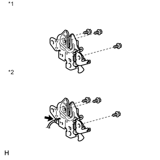
Text in Illustration *1 w/o Engine Hood Courtesy Switch *2 w/ Engine Hood Courtesy Switch
-
Install the hood lock with the 3 bolts
- Torque:
- 7.5 N*m { 77 kgf*cm, 66 in.*lbf }
-
w/ Engine Hood Courtesy Switch:
Connect the connector.
-
-
INSTALL BATTERY CLAMP SUB-ASSEMBLY
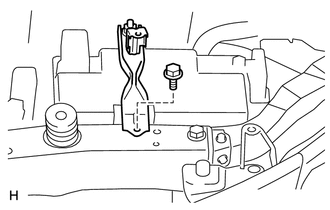
-
Install the battery clamp with the bolt.
-
-
INSTALL NO. 1 WATER HOSE CLAMP BRACKET
-
Install the hose clamp bracket with the 2 bolts.
- Torque:
- 5.0 N*m { 51 kgf*cm, 44 in.*lbf }
-
-
CHARGE REFRIGERANT
-
for HFC-134a(R134a):
-
for HFO-1234yf(R1234yf):
-
-
INSPECT HOOD SUB-ASSEMBLY
-
ADJUST HOOD SUB-ASSEMBLY
-
INSTALL RADIATOR SUPPORT OPENING COVER
-
WARM UP ENGINE
-
for HFC-134a(R134a):
-
for HFO-1234yf(R1234yf):
-
-
CHECK FOR REFRIGERANT GAS LEAK
-
for HFC-134a(R134a):
-
for HFO-1234yf(R1234yf):
-