AIR CONDITIONING UNIT(for Manual Air Conditioning System) INSTALLATION
CAUTION / NOTICE / HINT
Tech Tips
-
Use the same procedure for LHD and RHD vehicles.
-
The procedure listed below is for LHD vehicles.
-
A bolt without a torque specification is shown in the standard bolt chart Click here.
PROCEDURE
-
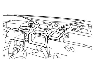
INSTALL AIR CONDITIONING UNIT ASSEMBLY
-
Install the air conditioning unit with the nut and bolt.
- Torque:
- 9.8 N*m { 100 kgf*cm, 87 in.*lbf }
-
Connect the drain cooler hose.
-
-
INSTALL INSTRUMENT PANEL REINFORCEMENT ASSEMBLY
-
Install the instrument panel reinforcement.
-
Install the instrument panel reinforcement with the bolts and screws.
-
-
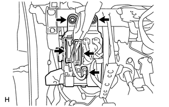
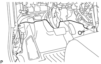
Attach the clamps and connectors to attach the wire harness.
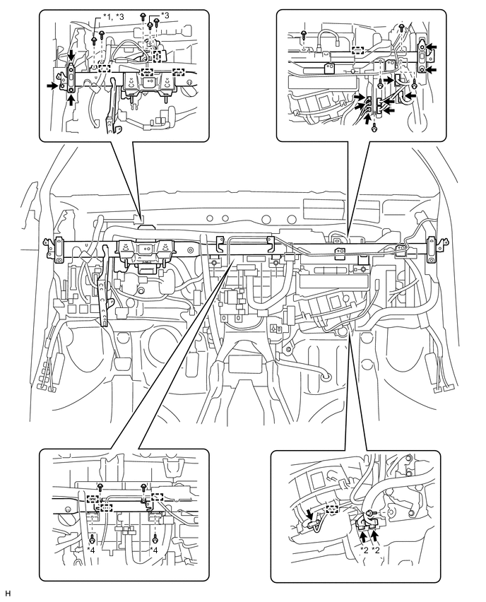
Text in Illustration *1 for Manual Transaxle *2 w/ PTC Heater *3 24 N*m (245 kgf*cm, 18 ft.*lbf) *4 9.8 N*m (100 kgf*cm, 87 in.*lbf)
-
-
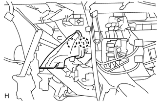
INSTALL NO. 1 INSTRUMENT PANEL BRACE SUB-ASSEMBLY
-
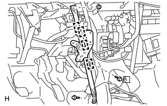
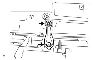
Install the brace with the 2 bolts and nut.
- Torque:
- for Bolt A
- 9.8 N*m { 100 kgf*cm, 87 in.*lbf }
-
Attach the clamps.
-
-
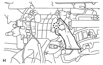
INSTALL NO. 2 INSTRUMENT PANEL BRACE SUB-ASSEMBLY
-
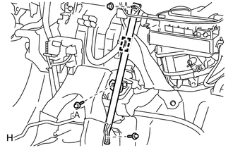
Install the brace with the 2 bolts and nut.
- Torque:
- for Bolt A
- 9.8 N*m { 100 kgf*cm, 87 in.*lbf }
-
Attach the clamp.
-
-
INSTALL MAIN BODY ECU (INSTRUMENT PANEL JUNCTION BLOCK ASSEMBLY)
-
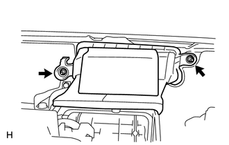
Install the main body ECU with the 2 bolts.
-
Connect the 3 connectors.
-
-
INSTALL POWER STEERING ECU ASSEMBLY
-
for LHD:
Install the power steering ECU assembly Click here.
-
for RHD:
Install the power steering ECU assembly Click here.
-
-
INSTALL CENTER INSTRUMENT PANEL TO COWL BRACE
-
Install the brace with the 2 bolts.
-
-
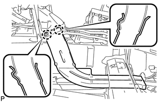
INSTALL AIR DUCT ASSEMBLY
-
Install the duct with the 2 nuts.
- Torque:
- 9.8 N*m { 100 kgf*cm, 87 in.*lbf }
-
-
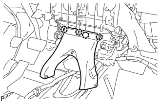
INSTALL DEFROSTER NOZZLE ASSEMBLY
-
Attach the 4 claws to install the defroster nozzle assembly.
-
-
INSTALL STEERING COLUMN ASSEMBLY
-
Install the steering column Click here.
-
-
INSTALL NO. 2 AIR DUCT SUB-ASSEMBLY
-
Attach the 2 claws to install the No. 2 air duct sub-assembly.
-
-
INSTALL NO. 1 AIR DUCT SUB-ASSEMBLY
-
Attach the 2 claws to install the No. 1 air duct sub-assembly.
-
-
INSTALL REAR NO. 1 AIR DUCT
-
Attach the 4 claws to install the rear No. 1 air duct.
-
-
INSTALL REAR NO. 2 AIR DUCT
-
Attach the 2 claws to install the rear No. 2 air duct.
-
Install the floor carpet with the clip.
-
-
INSTALL REAR NO. 3 AIR DUCT
-
Attach the 2 claws to install the rear No. 3 air duct.
-
Install the floor carpet with the clip.
-
-
INSTALL LOWER INSTRUMENT PANEL SUB-ASSEMBLY
-
Install the lower instrument panel Click here.
-
-
INSTALL UPPER INSTRUMENT PANEL SUB-ASSEMBLY
-
Install the upper instrument panel Click here.
-
-
CONNECT HEATER WATER INLET HOSE
-
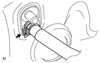
Connect the heater water inlet hose.
-
Using pliers, grip the claws of the clip and slide the clip.
-
-
CONNECT HEATER WATER OUTLET HOSE
-
Connect the heater water outlet hose.
-
Using pliers, grip the claws of the clip and slide the clip.
-
-
CONNECT AIR CONDITIONING TUBE ASSEMBLY (for HFC-134a(R134a))
-
Remove the attached vinyl tape from the tubes.
-
Sufficiently apply compressor oil to 2 new O-rings and the fitting surface of the air conditioning tube assembly.
Compressor oil ND-OIL 8 or equivalent -
Install the 2 O-rings to the air conditioning tube assembly.
-
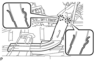
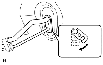
Connect the air conditioning tube assembly.
-
Attach the plate as shown in the illustration and install the bolt.
- Torque:
- 9.8 N*m { 100 kgf*cm, 87 in.*lbf }
-
-
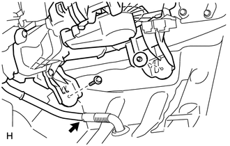
CONNECT AIR CONDITIONER TUBE AND ACCESSORY ASSEMBLY (for HFO-1234yf(R1234yf))
-
Remove the attached vinyl tape from the pipe and air conditioning unit.
-
Sufficiently apply compressor oil to 2 new O-rings and the fitting surface of the air conditioning tube and accessory.
Compressor oil ND-OIL 12 or equivalent -
Install the 2 O-rings to the air conditioning tube and accessory.
-
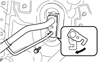
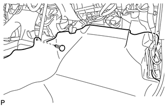
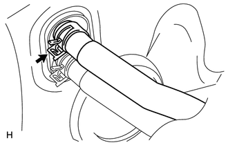
Securely connect the air conditioning tube and accessory to the air conditioning unit.
-
Move the hook connector in the direction indicated by the arrow in the illustration and install the bolt.
- Torque:
- 9.8 N*m { 100 kgf*cm, 87 in.*lbf }
-
-
INSTALL COWL TOP OUTER PANEL
-
INSTALL FRONT WIPER MOTOR AND BRACKET
-
Install the front wiper motor and bracket Click here.
-
-
CONNECT CABLE TO NEGATIVE BATTERY TERMINAL
Note
When disconnecting the cable, some systems need to be initialized after the cable is reconnected Click here.
-
CHECK SRS WARNING LIGHT
-
Check the SRS warning light Click here.
-
-
ADD ENGINE COOLANT
-
for 1ZR-FAE:
Add engine coolant Click here.
-
for 2ZR-FAE:
Add engine coolant Click here.
-
for 3ZR-FAE:
Add engine coolant Click here.
-
-
CHARGE REFRIGERANT
-
for HFC-134a(R134a):
-
for HFO-1234yf(R1234yf):
-
-
WARM UP ENGINE
-
for HFC-134a(R134a):
-
for HFO-1234yf(R1234yf):
-
-
INSPECT FOR COOLANT LEAK
-
for 1ZR-FAE:
Inspect for engine coolant leak Click here.
-
for 2ZR-FAE:
Inspect for engine coolant leak Click here.
-
for 3ZR-FAE:
Inspect for engine coolant leak Click here.
-
-
CHECK FOR REFRIGERANT GAS LEAK
-
for HFC-134a(R134a):
-
for HFO-1234yf(R1234yf):
-
-
INSTALL NO. 1 ENGINE UNDER COVER (for Rough Road Area Specification Vehicles)
-
INSTALL NO. 1 ENGINE UNDER COVER
-
INSTALL FRONT LOWER BUMPER ABSORBER
-
INSTALL RADIATOR SUPPORT OPENING COVER
-
INSTALL NO. 2 CYLINDER HEAD COVER