METER / GAUGE SYSTEM Meter Illumination is Always Dark
DESCRIPTION
In this circuit, the combination meter assembly receives auto dimmer signals from the main body ECU through the CAN communication line when the headlight dimmer switch is set to AUTO. When the combination meter receives an auto dimmer signal, it dims the meter illumination. The main body ECU determines whether it is daytime, twilight or nighttime based on the waveform transmitted from the automatic light control sensor that is built into the rain sensor. If the main body ECU determines that it is daytime, the ECU does not send auto dimmer signals.
Tech Tips
When the meter illumination does not dim at night even if the headlight dimmer switch is set to AUTO, there may be a malfunction in the rain sensor, main body ECU, CAN communication system, wire harnesses, connectors or combination meter assembly.
WIRING DIAGRAM
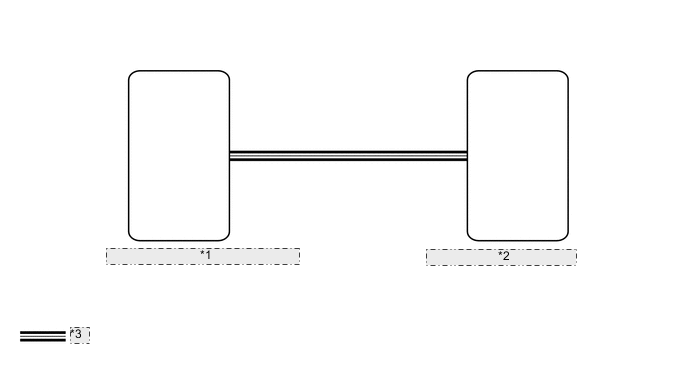
| *1 | Main Body ECU (Instrument Panel Junction Block Assembly) |
| *2 | Combination Meter Assembly |
| *3 | CAN Communication Line |
CAUTION / NOTICE / HINT
Note
As the door control battery is installed between the vehicle battery and main body ECU (instrument panel junction block assembly), first perform the inspections in On-Vehicle Inspection to confirm that there are no malfunctions in the power source circuit for the main body ECU (instrument panel junction block assembly) before performing this troubleshooting procedure Click here.
PROCEDURE
-
CHECK FOR DTC (CAN COMMUNICATION SYSTEM)
-
Check for DTCs Click here.
Result Result Proceed to No DTCs are output A CAN communication system DTC is output B
B 
GO TO CAN COMMUNICATION SYSTEM Click here
A 
-
-
CHECK FOR DTC (LIGHTING SYSTEM)
-
Check for DTCs Click here.
Result Result Proceed to No DTCs are output A Lighting system DTC is output B
B
GO TO LIGHTING SYSTEM Click here
A
-
-
READ VALUE USING GTS (DIMMER SW)
-
Using the GTS, read the Data List Click here.
Main Body Tester Display Measurement Item/Range Normal Condition Diagnostic Note Dimmer SW Headlight dimmer switch signal / OFF or ON OFF: Headlight dimmer switch off
ON: Headlight dimmer switch on
- OK Tester display changes according to operation of headlight dimmer switch. Tech Tips
Refer to the sensitivity setting in the customization table of the automatic light control system Click here.
NG
GO TO LIGHTING SYSTEM Click here
OK
-
-
REPLACE COMBINATION METER ASSEMBLY
-
Temporarily replace the combination meter with a new or normally functioning one Click here.
NEXT
-
-
CHECK METER / GAUGE SYSTEM
-
Perform an operation check and check that the operation of the combination meter returns to normal Click here.
OK Operation of combination meter returns to normal.
OK
END (COMBINATION METER IS DEFECTIVE)
NG
REPLACE MAIN BODY ECU (INSTRUMENT PANEL JUNCTION BLOCK ASSEMBLY)
-