METER / GAUGE SYSTEM Entire Combination Meter does not Operate
DESCRIPTION
This circuit is the power source circuit for the meter. This circuit provides two types of power sources; one is a constant power source mainly used as a backup power source, and the other is an IG power source mainly used for signal transmission. The constant power source is mainly used as a backup power source for the meter CPU, however, it is also used for CAN communication. If a voltage of 12 V is not applied to terminal IG+ when the ignition switch is turned to ON, the combination meter does not operate.
WIRING DIAGRAM
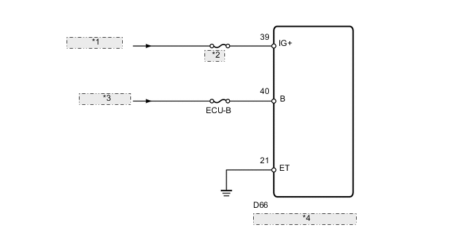
| *1 | from IG2 Relay |
| *2 | METER |
| *3 | from Battery |
| *4 | Combination Meter Assembly |
CAUTION / NOTICE / HINT
Note
Inspect the fuses for circuits related to this system before performing the following inspection procedure.
PROCEDURE
-
CHECK HARNESS OR CONNECTOR (COMBINATION METER ASSEMBLY - BATTERY AND BODY GROUND)
-
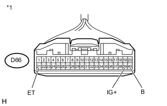
Text in Illustration *1 Front view of wire harness connector
(to Combination Meter Assembly)
Disconnect the D66 combination meter assembly connector.
-
Measure the resistance according to the value(s) in the table below.
Standard Resistance Tester Connection Condition Specified Condition D66-21 (ET) - Body ground Always Below 1 Ω -
Measure the voltage according to the value(s) in the table below.
Standard Voltage Tester Connection Condition Specified Condition D66-39 (IG+) - Body ground Ignition switch ON 11 to 14 V D66-40 (B) - Body ground Always 11 to 14 V
OK 
REPLACE COMBINATION METER ASSEMBLY Click here
NG
REPAIR OR REPLACE HARNESS OR CONNECTOR
-