THEFT DETERRENT SYSTEM, Diagnostic DTC:B2762, B2764
| DTC Code | DTC Name |
|---|---|
| B2762 | Intrusion Sensor Signal Circuit Malfunction |
| B2764 | Short to GND in Intrusion Sensor Signal Circuit |
DESCRIPTION
-
The intrusion sensor conducts a self-diagnosis immediately after power is supplied to the sensor (when the theft deterrent system is set).
-
If a malfunction is detected in the IOUT line, the main body ECU (instrument panel junction block) stores DTC B2762.
-
B2764 DTC is stored when terminal IOUT of the intrusion sensor has not received a signal for 5 seconds or more.
| DTC Code | DTC Detection Condition | Trouble Area |
|---|---|---|
| B2762 | After a normal/trouble signal is output from the intrusion sensor as result of self-diagnosis, either of the following malfunctions is detected:
|
|
| B2764 | After normal/trouble signal is output from the intrusion sensor as result of self-diagnosis, the following malfunction is detected: Terminal IOUT of the intrusion sensor has not received signal for 5 seconds or more. |
|
WIRING DIAGRAM
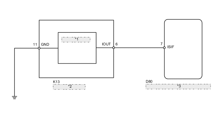
| *1 | Intrusion Sensor |
| *2 | Map Light Assembly |
| *3 | Main Body ECU (Instrument Panel Junction Block) |
CAUTION / NOTICE / HINT
Note
As the door control battery is installed between the vehicle battery and main body ECU (instrument panel junction block assembly), first perform the inspections in On-Vehicle Inspection to confirm that there are no malfunctions in the power source circuit for the main body ECU (instrument panel junction block assembly) before performing this troubleshooting procedure Click here.
PROCEDURE
-
CHECK HARNESS AND CONNECTOR (MAP LIGHT - MAIN BODY ECU [INSTRUMENT PANEL JUNCTION BLOCK] AND BODY GROUND)
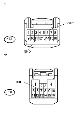
Text in Illustration *1 Front view of wire harness connector
(to Map Light)
*2 Front view of wire harness connector
(to Main Body ECU [Instrument Panel Junction Block])
-
Disconnect the K13 light connector.
-
Disconnect the D80 ECU connector.
-
Measure the resistance according to the value(s) in the table below.
Standard Resistance Tester Connection Condition Specified Condition K13-6 (IOUT) - D80-7 (ISIF) Always Below 1 Ω K13-6 (IOUT) or D80-7 (ISIF) - Body ground Always 10 kΩ or higher K13-11 (GND) - Body ground Always Below 1 Ω
NG 
REPAIR OR REPLACE HARNESS OR CONNECTOR
OK 
-
-
CHECK MAP LIGHT ASSEMBLY
-
Temporarily replace the map light assembly with a new or normally functioning one Click here.
-
Check if DTC B2764 is not output.
OK DTC B2762 or B2764 is not output.
OK
END (MAP LIGHT ASSEMBLY IS FAULTY)
NG
REPLACE MAIN BODY ECU (INSTRUMENT PANEL JUNCTION BLOCK)
-