ENTRY AND START SYSTEM(for Start Function), Diagnostic DTC:B2285
| DTC Code | DTC Name |
|---|---|
| B2285 | Steering Lock Position Signal Circuit Malfunction |
DESCRIPTION
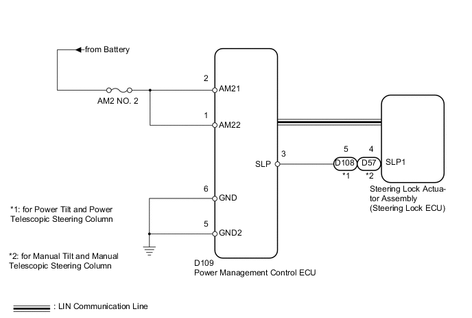
The power management control ECU and the steering lock actuator (steering lock ECU) are connected by a cable and the LIN communication line. This DTC is stored when the cable information of the steering lock position signal and LIN information of the steering lock position signal are inconsistent.
Tech Tips
When the power management control ECU is replaced with a new one and the cable is connected to the negative (-) battery terminal, the power source mode is reset to on (IG). When the battery is removed and reinstalled, the power source mode that was selected when the battery was removed is restored.
| DTC Code | DTC Detection Condition | Trouble Area |
|---|---|---|
| B2285 | The cable information of the steering lock position signal and LIN information of the steering lock position signal are inconsistent. |
|
WIRING DIAGRAM
CAUTION / NOTICE / HINT
Note
-
When using the intelligent tester with the engine switch off to troubleshoot: Connect the intelligent tester to the vehicle, and turn a courtesy light switch on and off at 1.5 second intervals until communication between the intelligent tester and vehicle begins.
-
Before performing the inspection, check that there are no problems related to the CAN communication system and LIN communication system.
-
Inspect the fuses for circuits related to this system before performing the following inspection procedure.
Tech Tips
After replacing the steering lock actuator assembly (steering lock ECU), perform the key ID code registration. Refer to the Service Bulletin for the registration procedure.
PROCEDURE
-
CHECK FOR DTC (LIN COMMUNICATION SYSTEM)
-
Clear the DTCs Click here.
-
Check for DTCs Click here.
OK LIN communication system DTCs B2287 and B2785 are not output simultaneously.
NG 
GO TO DTC B2287 Click here
OK 
-
-
CHECK HARNESS AND CONNECTOR (BATTERY - POWER MANAGEMENT CONTROL ECU)
-
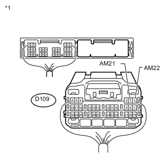
Text in Illustration *1 Rear view of wire harness connector
(to Power Management Control ECU)
Disconnect the D109 power management control ECU connector.
-
Measure the voltage according to the value(s) in the table below.
Standard Voltage Tester Connection Condition Specified Condition D109-2 (AM21) - Body ground Always 9.5 to 16 V D109-1 (AM22) - Body ground
NG
REPAIR OR REPLACE HARNESS OR CONNECTOR
OK
-
-
CHECK HARNESS AND CONNECTOR (POWER MANAGEMENT CONTROL ECU - BODY GROUND)
-
Disconnect the D109 power management control ECU connector.
-
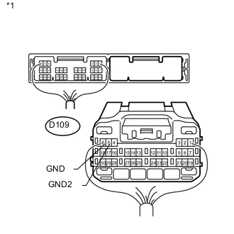
Text in Illustration *1 Rear view of wire harness connector
(to Power Management Control ECU)
Measure the resistance according to the value(s) in the table below.
Standard Resistance Tester Connection Condition Specified Condition D109-6 (GND) - Body ground Always Below 1 Ω D109-5 (GND2) - Body ground
NG
REPAIR OR REPLACE HARNESS OR CONNECTOR
OK
-
-
INSPECT STEERING LOCK ACTUATOR ASSEMBLY (STEERING LOCK ECU)
-
for Manual Tilt and Manual Telescopic Steering Column:
-
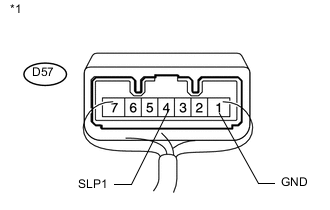
Text in Illustration *1 Component with harness connected
(Steering Lock ECU)
Measure the resistance according to the value(s) in the table below.
Standard Resistance Tester Connection Condition Specified Condition D57-4 (SLP1) - Body ground Steering lock locked 10 kΩ or higher D57-4 (SLP1) - Body ground Steering lock released Below 1 Ω
-
-
for Power Tilt and Power Telescopic Steering Column:
-
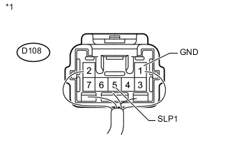
Text in Illustration *1 Component with harness connected
(Steering Lock ECU)
Measure the resistance according to the value(s) in the table below.
Standard Resistance Tester Connection Condition Specified Condition D108-5 (SLP1) - Body ground Steering lock locked 10 kΩ or higher D108-5 (SLP1) - Body ground Steering lock released Below 1 Ω Result Result Proceed to OK A NG (for Power Tilt and Power Telescopic Steering Column) B NG (for Manual Tilt and Manual Telescopic Steering Column) C
-
B
REPLACE STEERING LOCK ACTUATOR (STEERING LOCK ECU) Click here
C
REPLACE STEERING LOCK ACTUATOR (STEERING LOCK ECU) Click here
A
-
-
CHECK HARNESS AND CONNECTOR (POWER MANAGEMENT CONTROL ECU - STEERING LOCK ECU)
-
for Manual Tilt and Manual Telescopic Steering Column:
-
Disconnect the D109 power management control ECU connector.
-
Disconnect the D57 steering lock ECU connector.
-
Measure the resistance according to the value(s) in the table below.
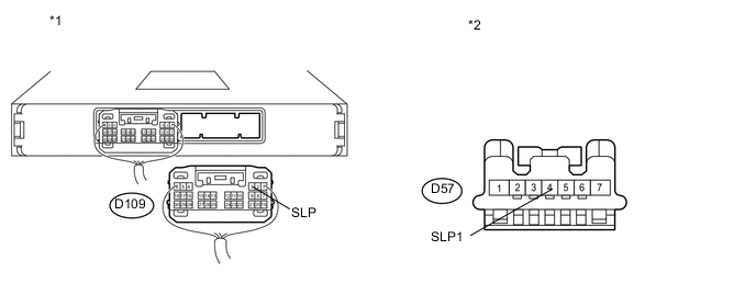
Standard Resistance Tester Connection Condition Specified Condition D57-4 (SLP1) - D109-3 (SLP) Always Below 1 Ω D57-4 (SLP1) or D109-3 (SLP) - Body ground Always 10 kΩ or higher Text in Illustration *1 Rear view of wire harness connector
(to Power Management Control ECU)
*2 Front view of wire harness connector
(to Steering Lock ECU)
-
-
for Power Tilt and Power Telescopic Steering Column:
-
Disconnect the D109 power management control ECU connector.
-
Disconnect the D108 steering lock ECU connector.
-
Measure the resistance according to the value(s) in the table below.
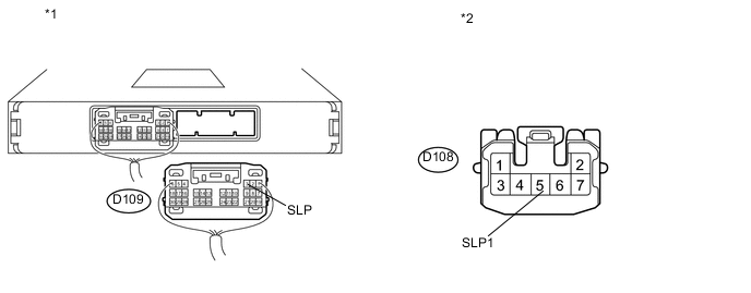
Standard Resistance Tester Connection Condition Specified Condition D108-5 (SLP1) - D109-3 (SLP) Always Below 1 Ω D108-5 (SLP1) or D109-3 (SLP) - Body ground Always 10 kΩ or higher Text in Illustration *1 Rear view of wire harness connector
(to Power Management Control ECU)
*2 Front view of wire harness connector
(to Steering Lock ECU)
-
NG
REPAIR OR REPLACE HARNESS OR CONNECTOR
OK
-
-
READ VALUE USING INTELLIGENT TESTER (STEERING UNLOCK SWITCH)
-
Connect the intelligent tester to the DLC3.
-
Turn the engine switch on (IG).
-
Turn the intelligent tester on.
-
Enter the following menus: Body / Power Source Control / Data List.
-
According to the display on the intelligent tester, read the Data List.
Power Source Control Tester Display Measurement Item/Range Normal Condition Diagnostic Note Steering Unlock Switch Steering lock condition / ON or OFF ON: Steering lock released (Engine switch on (ACC))
OFF: Steering lock locked (Engine switch off)
- OK ON (steering lock released) or OFF (steering lock locked) appears on the screen according to the steering lock condition. Result Result Proceed to OK (for Power Tilt and Power Telescopic Steering Column) A OK (for Manual Tilt and Manual Telescopic Steering Column) B NG C
A
REPLACE STEERING LOCK ACTUATOR (STEERING LOCK ECU) Click here
B
REPLACE STEERING LOCK ACTUATOR (STEERING LOCK ECU) Click here
C
REPLACE POWER MANAGEMENT CONTROL ECU Click here
-